Asus P5VD2 VM P5VD2-VM English Edition User's Manual - Page 40
WIFI-AP Solo LED indicator Only for P5V-VM SE DH. - pci
 |
UPC - 610839148318
View all Asus P5VD2 VM manuals
Add to My Manuals
Save this manual to your list of manuals |
Page 40 highlights
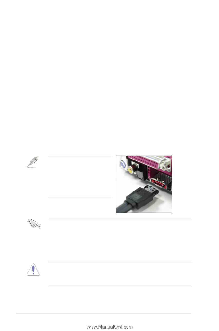
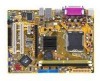
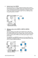
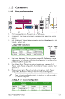
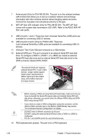
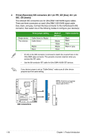
7. Antenna jack (Only for P5V-VM SE DH). This port is on the onboard wireless LAN module that allows you to set up a wireless network and exchange information with other wireless devices without tangling cables and wires. Connect the moveable omni-directional antenna to this jack. 8. WIFI-AP Solo LED indicator (Only for P5V-VM SE DH). The WIFI-AP Solo comes with a green data transmission LED (AIR). Refer to the ASUS WiFi-AP Solo user guide. 9. USB 2.0 ports 1 and 2. These two 4-pin Universal Serial Bus (USB) ports are available for connecting USB 2.0 devices. 10. USB 2.0 ports 3 and 4 (Only for P5VD2-VM). These two 4-pin Universal Serial Bus (USB) ports are available for connecting USB 2.0 devices. 11. VGA port. This 15-pin VGA port connects to a VGA monitor. 12. External SATA port. This port connects to an external Serial ATA hard disk drive. To configure a RAID 0, a RAID 1, or a JBOD set, install an external Serial ATA hard disk drive and an internal Serial ATA hard disk drive to the SATA connector labeled SATA_RAID1. The external SATA port supports external Serial ATA 1.5 and 3 Gb/s devices. Longer cables support higher power requirements to deliver signal up to two meters away, and enables improved hot-swap function. • Before creating a RAID set using Serial ATA hard disks, make sure that you have connected the Serial ATA signal cable and installed Serial ATA hard disk drives; otherwise, you cannot enter the JMicron RAID utility and SATA BIOS setup during POST. • If you intend to create a RAID configuration using this connector, set the JMicron RAID controller item in the BIOS to [RAID Mode]. See section "2.4.4 Onboard Devices Configuration" for details. • DO NOT insert a different connector to this port. • DO NOT unplug the external Serial ATA box when a RAID 0 or JBOD is configured. • PCI-E x1 and eSATA cannot be used simultaneously. 13. PS/2 keyboard port (purple). This port is for a PS/2 keyboard. 1-28 Chapter 1: Product introduction
-
 1
1 -
2
-
3
-
4
-
5
-
6
-
7
-
8
-
9
-
10
-
11
-
12
-
13
-
14
-
15
-
16
-
17
-
18
-
19
-
20
-
21
-
22
-
23
-
24
-
25
-
26
-
27
-
28
-
29
-
30
-
31
-
32
-
33
-
34
-
 35
35 -
 36
36 -
 37
37 -
 38
38 -
 39
39 -
 40
40 -
 41
41 -
 42
42 -
 43
43 -
 44
44 -
 45
45 -
46
-
47
-
48
-
49
-
50
-
51
-
52
-
53
-
54
-
55
-
56
-
57
-
58
-
59
-
60
-
61
-
62
-
63
-
64
-
65
-
66
-
67
-
68
-
69
-
70
-
71
-
72
-
73
-
74
-
75
-
76
-
77
-
78
-
79
-
80
-
81
-
82
-
83
-
84
-
85
-
86
-
87
-
88
-
89
-
90
-
91
-
92
-
93
-
94
-
95
-
96
-
97
-
98
-
99
-
100
-
101
-
102
-
103
-
104
-
105
-
106
-
107
-
108
-
109
-
110
 |
 |