Asus P7H55-M LE User Manual - Page 21
P7H55-M LE System panel connector - motherboard cpu
 |
View all Asus P7H55-M LE manuals
Add to My Manuals
Save this manual to your list of manuals |
Page 21 highlights
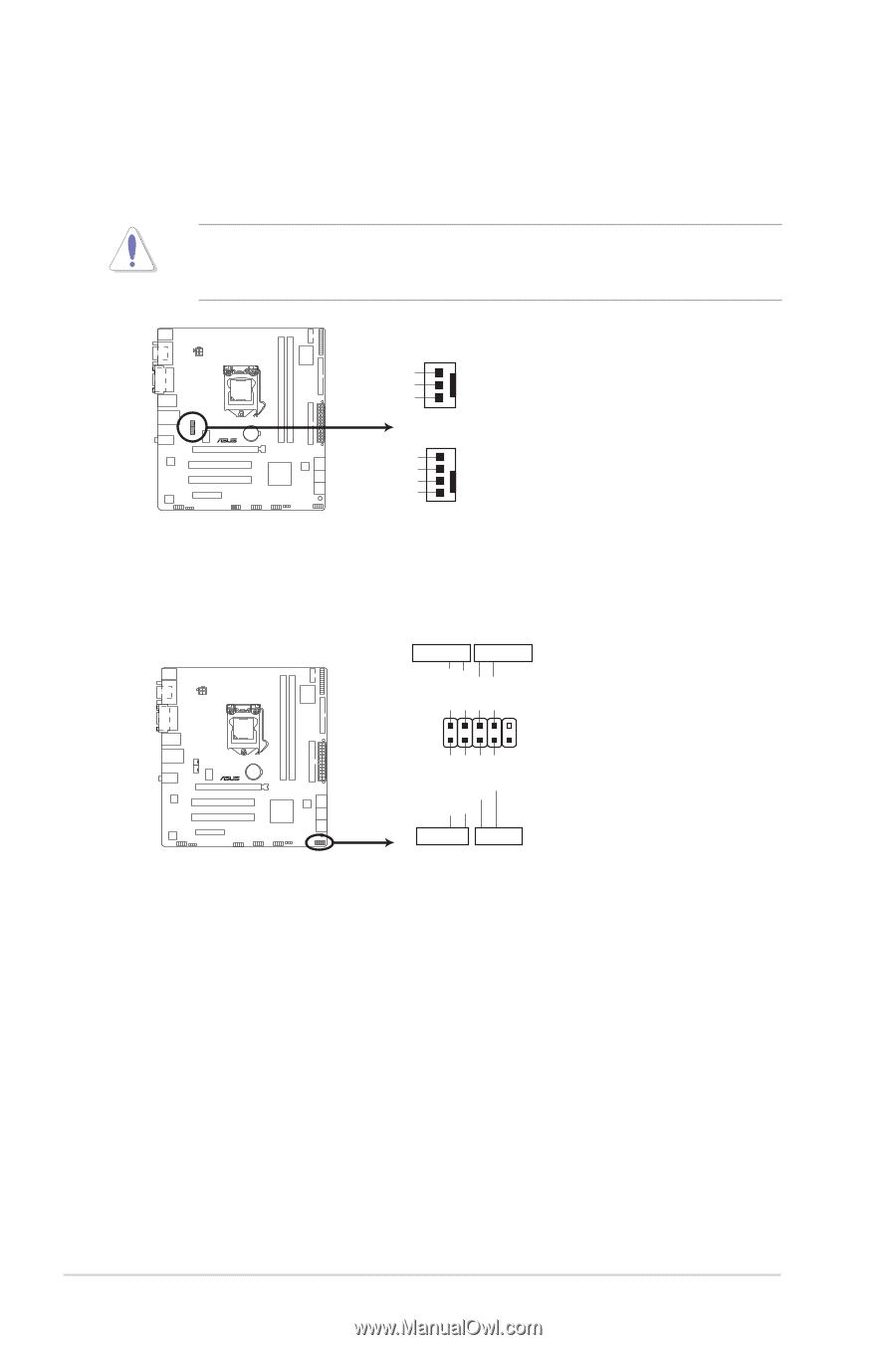
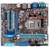
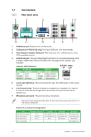
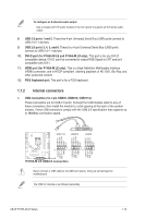
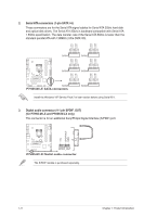
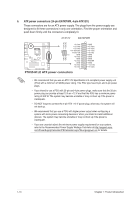
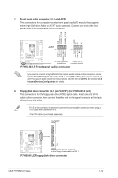
4. CPU and Chassis fan connectors (4-pin CPU_FAN, 3-pin CHA_FAN) Connect the fan cables to the fan connectors on the motherboard, making sure that the black wire of each cable matches the ground pin of the connector. DO NOT forget to connect the fan cables to the fan connectors. Insufficient air flow inside the system may damage the motherboard components. They are not jumpers! DO NOT place jumper caps on the fan connectors. CHA_FAN Rotation +12V GND P7H55-M LE CPU_FAN CPU FAN PWM CPU FAN IN CPU FAN PWR GND P7H55-M LE fan connectors 5. System panel connector (10-1 pin F_PANEL) This connector supports several chassis-mounted functions. PWR LED PWR BTN PLED+ PLEDPWR GND IDE_LED+ IDE_LED- Ground Reset F_PANEL PIN 1 P7H55-M LE HD_LED RESET P7H55-M LE System panel connector • System power LED (2-pin PLED) This 2-pin connector is for the system power LED. Connect the chassis power LED cable to this connector. The system power LED lights up when you turn on the system power, and blinks when the system is in sleep mode. • Hard disk drive activity LED (2-pin +HDLED) This 2-pin connector is for the HDD Activity LED. Connect the HDD Activity LED cable to this connector. The IDE LED lights up or flashes when data is read from or written to the HDD. • Power/Soft-off button (2-pin PWRBTN) This 2-pin connector is for the system power button. • Reset button (2-pin RESET) This 2-pin connector is for the chassis-mounted reset button for system reboot without turning off the system power. ASUS P7H55-M LE Series 1-12
-
 1
1 -
2
-
3
-
4
-
5
-
6
-
7
-
8
-
9
-
10
-
11
-
12
-
13
-
14
-
15
-
 16
16 -
 17
17 -
 18
18 -
 19
19 -
 20
20 -
 21
21 -
 22
22 -
 23
23 -
 24
24 -
 25
25 -
 26
26 -
27
-
28
-
29
-
30
-
31
-
32
-
33
-
34
-
35
-
36
-
37
-
38
-
39
-
40
-
41
-
42
-
43
-
44
-
45
-
46
-
47
-
48
-
49
 |
 |