Asus P7H55-M LE User Manual - Page 23
P7H55-M LE Front panel audio connector
 |
View all Asus P7H55-M LE manuals
Add to My Manuals
Save this manual to your list of manuals |
Page 23 highlights
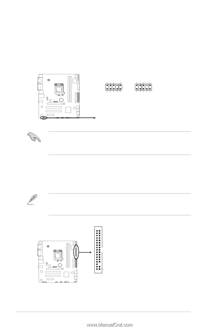
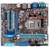
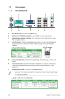
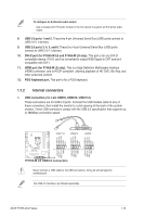
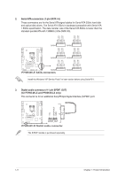
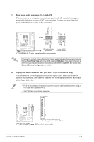
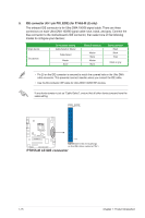
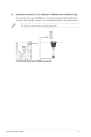
7. Front panel audio connector (10-1 pin AAFP) This connector is for a chassis-mounted front panel audio I/O module that supports either High Definition Audio or AC`97 audio standard. Connect one end of the front panel audio I/O module cable to this connector. SENSE2_RETUR SENSE1_RETUR PRESENCE# AGND NC NC NC GND AAFP PIN 1 PIN 1 MIC2 MICPWR Line out_R NC Line out_L PORT2 L SENSE_SEND PORT2 R PORT1 R PORT1 L P7H55-M LE HD-audio-compliant Legacy AC'97 pin definition compliant definition P7H55-M LE Front panel audio connector If you want to connect a high-definition front panel audio module to this connector, ensure that the Front Panel Type item in the BIOS is set to [HD Audio]. If you want to connect an AC97 front panel audio module to this connector, set the item to [AC97]. See section 2.4.3 Onboard Devices Configuration for details. 8. Floppy disk drive connector (34-1 pin FLOPPY) (for P7H55-M LE only) This connector is for the floppy disk drive (FDD) signal cable. Insert one end of the cable to this connector, then connect the other end to the signal connector at the back of the floppy disk drive. • Pin 5 on the connector is removed to prevent incorrect cable connection when using a FDD cable with a covered Pin 5. • The FDD cable is purchased separately. FLOPPY PIN1 P7H55-M LE NOTE:Orient the red markings on the floppy ribbon cable to PIN 1. P7H55-M LE Floppy disk drive connector ASUS P7H55-M LE Series 1-14
-
 1
1 -
2
-
3
-
4
-
5
-
6
-
7
-
8
-
9
-
10
-
11
-
12
-
13
-
14
-
15
-
16
-
17
-
 18
18 -
 19
19 -
 20
20 -
 21
21 -
 22
22 -
 23
23 -
 24
24 -
 25
25 -
 26
26 -
 27
27 -
 28
28 -
29
-
30
-
31
-
32
-
33
-
34
-
35
-
36
-
37
-
38
-
39
-
40
-
41
-
42
-
43
-
44
-
45
-
46
-
47
-
48
-
49
 |
 |