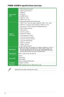
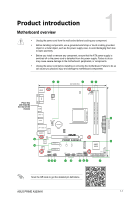
Asus PRIME A320M-K PRIME A320M-K Users ManualEnglish - Page 11
AMD A320 Serial ATA 6.0Gb/s connectors 7-pin SATA6G_1~4, Clear RTC RAM 2-pin CLRTC - bios
 |
View all Asus PRIME A320M-K manuals
Add to My Manuals
Save this manual to your list of manuals |
Page 11 highlights
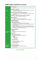
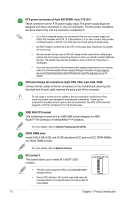
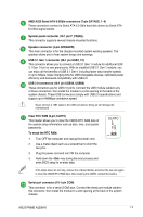
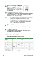
AMD A320 Serial ATA 6.0Gb/s connectors (7-pin SATA6G_1~4) These connectors connect to Serial ATA 6.0 Gb/s hard disk drives via Serial ATA 6.0 Gb/s signal cables. System panel connector (10-1 pin F_PANEL) This connector supports several chassis-mounted functions. Speaker connector (4-pin SPEAKER) This 4-pin connector is for the chassis-mounted system warning speaker. The speaker allows you to hear system beeps and warnings. USB 3.1 Gen 1 connector (20-1 pin USB3_12) This connector allows you to connect a USB 3.1 Gen 1 module for additional USB 3.1 Gen 1 front or rear panel ports. With an installed USB 3.1 Gen 1 module, you can enjoy all the benefits of USB 3.1 Gen 1 including faster data transfer speeds of up to 5Gbps, faster charging time for USB-chargeable devices, optimized power efficiency and backward compatibility with USB 2.0. USB 2.0 connectors (10-1 pin USB34, USB56) These connectors are for USB 2.0 ports. Connect the USB module cable to any of these connectors, then install the module to a slot opening at the back of the system chassis. These USB connectors comply with USB 2.0 specifications and support up to 480Mbps connection speed. Never connect a 1394 cable to the USB connectors. Doing so will damage the motherboard! Clear RTC RAM (2-pin CLRTC) This header allows you to clear the CMOS RTC RAM data of the system setup information such as date, time, and system passwords. To erase the RTC RAM: 1. Turn OFF the computer and unplug the power cord. 2. Use a metal object such as a screwdriver to short the two pins. 3. Plug the power cord and turn ON the computer. 4. Hold down the key during the boot process and enter BIOS setup to re-enter data. +3V_BAT GND CLRTC PIN 1 If the steps above do not help, remove the onboard battery and short the two pins again to clear the CMOS RTC RAM data. After clearing the CMOS, reinstall the battery. Serial port connector (10-1 pin COM) This connector is for a serial (COM) port. Connect the serial port module cable to this connector, then install the module to a slot opening at the back of the system chassis. ASUS PRIME A320M-K 1-3
-
 1
1 -
2
-
3
-
4
-
5
-
 6
6 -
 7
7 -
 8
8 -
 9
9 -
 10
10 -
 11
11 -
 12
12 -
 13
13 -
 14
14 -
 15
15 -
 16
16 -
17
-
18
-
19
-
20
-
21
-
22
-
23
-
24
-
25
-
26
-
27
-
28
 |
 |