Asus PRIME A320M-K PRIME A320M-K Users ManualEnglish - Page 12
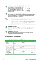
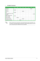
IRQ assignments for this motherboard, For AMD AM4 A-series/Athlon™ Series processors
 |
View all Asus PRIME A320M-K manuals
Add to My Manuals
Save this manual to your list of manuals |
Page 12 highlights
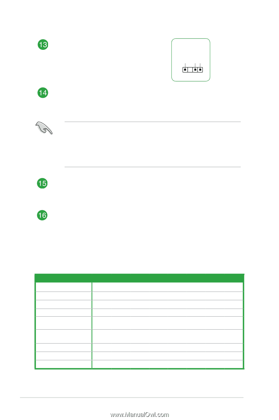
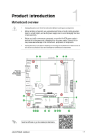
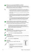
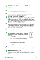
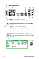
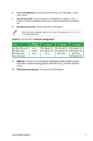
Digital audio connector (4-1 pin SPDIF_OUT) This connector is for an additional Sony/Philips Digital Interface (S/PDIF) port. Connect the S/ PDIF Out module cable to this connector, then install the module to a slot opening at the back of the system chassis. +5V SPDIFOUT GND PIN 1 SPDIF_OUT Front panel audio connector (10-1 pin AAFP) This connector is for a chassis-mounted front panel audio I/O module that supports either HD Audio or legacy AC`97 audio standard. Connect one end of the front panel audio I/O module cable to this connector. • We recommend that you connect a high-definition front panel audio module to this connector to avail of the motherboard's high-definition audio capability. • If you want to connect a high-definition front panel audio module to this connector, set the Front Panel Type item in the BIOS setup to [HD Audio]. If you want to connect an AC'97 front panel audio module to this connector, set the item to [AC97]. By default, this connector is set to [HD Audio]. PCI Express 2.0 x1 slots This motherboard has two PCI Express 2.0 x1 slots that support PCI Express x1 network cards, SCSI cards, and other cards that comply with the PCI Express specifications. PCI Express 3.0 / 2.0 x16 slot This motherboard supports one PCI Express 3.0 / 2.0 x16 graphic card that complies with the PCI Express specifications. IRQ assignments for this motherboard • For AMD AM4 A-series/Athlon™ Series processors A B C D E PCIEx16_1 - - - shared - PCIEx1_1 shared - - - - PCIEx1_2 - - - shared - M.2 - - - shared - APU USB3.1 Gen 1 XHCI controller - - shared - - AMD Promonotry Chip XHCI controller shared - - - - SATA controller - - - shared - HD audio controller - - - - - Realtek LAN controller - - shared - - F G H - - - - - - - - - - - - - - - - - - - - - - shared - - - - 1-4 Chapter 1: Product introduction
-
 1
1 -
2
-
3
-
4
-
5
-
6
-
 7
7 -
 8
8 -
 9
9 -
 10
10 -
 11
11 -
 12
12 -
 13
13 -
 14
14 -
 15
15 -
 16
16 -
 17
17 -
18
-
19
-
20
-
21
-
22
-
23
-
24
-
25
-
26
-
27
-
28
 |
 |