Asus PRIME B350M-E User Guide - Page 12
System power LED 2-pin PWR_LED, Hard disk drive activity LED 2-pin HDD_LED
 |
View all Asus PRIME B350M-E manuals
Add to My Manuals
Save this manual to your list of manuals |
Page 12 highlights
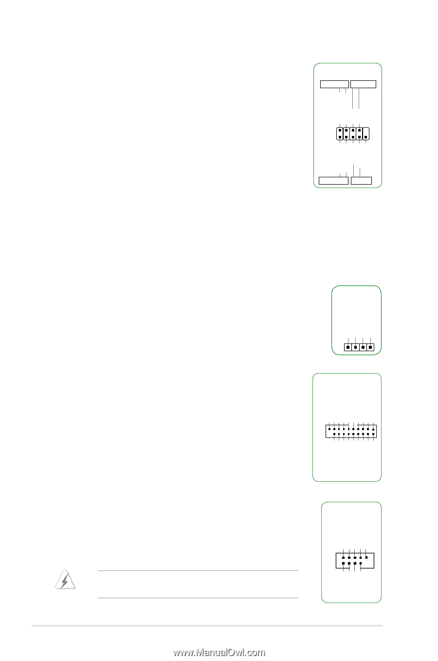
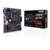
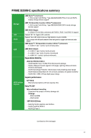
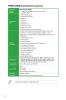
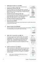
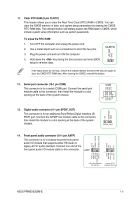
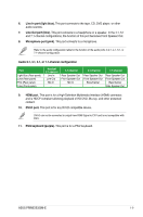
7. System panel connector (10-1 pin PANEL) This connector supports several chassis-mounted functions. • System power LED (2-pin PWR_LED) F_PANEL +PWR LED PWR BTN PWR_LED+ PWR_LEDPWR GND This 2-pin connector is for the system power LED. Connect the chassis power LED cable to this connector. The system power LED lights up when you turn on the system power, and blinks when the system is in sleep mode. PIN 1 • Hard disk drive activity LED (2-pin HDD_LED) HDD_LED+ HDD_LED- Ground HWRST# (NC) This 2-pin connector is for the HDD Activity LED. Connect the HDD Activity LED cable to this connector. The HDD LED lights up or flashes when data is read from or written to the HDD. +HDD_LED RESET • ATX power button/soft-off button (2-pin PWR_BTN) This connector is for the system power button. • Reset button (2-pin RESET) This 2-pin connector is for the chassis-mounted reset button for system reboot without turning off the system power. 8. Speaker connector (4-pin SPEAKER) The 4-pin connector is for the chassis-mounted system warning speaker. SPEAKER The speaker allows you hear system beeps and warnings. +5V GND GND Speaker Out USB3+5V IntA_P1_SSRXIntA_P1_SSRX+ GND IntA_P1_SSTXIntA_P1_SSTX+ GND IntA_P1_DIntA_P1_D+ GND PIN 1 9. USB 3.1 Gen 1 connector (20-1 pin USB3_12) USB3_12 This connector allows you to connect a USB 3.1 Gen 1 module for additional USB 3.1 Gen 1 front or rear panel ports. With an installed USB 3.1 Gen 1 module, you can enjoy all the benefits of USB 3.1 Gen 1 including faster data transfer speeds of up PIN 1 to 5Gbps, faster charging time for USB-chargeable devices, optimized power efficiency and backward compatibility with USB 2.0. USB3+5V IntA_P2_SSRXIntA_P2_SSRX+ GND IntA_P2_SSTXIntA_P2_SSTX+ GND IntA_P2_DIntA_P2_D+ USB+5V USB_P3USB_P3+ GND NC 10. USB 2.0 connectors (10-1 pin USB3~6) These connectors are for USB 2.0 ports. Connect the USB module cable to any of these connector, then install the module to a slot opening at the back of the system chassis. These USB connectors comply with USB 2.0 specifications and supports up to 480Mbps connection speed. Never connect a 1394 cable to the USB connectors. Doing so will damage the motherboard! USB34 PIN 1 USB+5V USB_P4USB_P4+ GND 1-4 Chapter 1: Product introduction
-
 1
1 -
2
-
3
-
4
-
5
-
6
-
 7
7 -
 8
8 -
 9
9 -
 10
10 -
 11
11 -
 12
12 -
 13
13 -
 14
14 -
 15
15 -
 16
16 -
 17
17 -
18
-
19
-
20
-
21
-
22
-
23
-
24
-
25
-
26
-
27
-
28
-
29
-
30
-
31
-
32
-
33
-
34
-
35
-
36
-
37
 |
 |