Asus PRIME B360M-A Users Manual English - Page 12
B360 Serial ATA 6.0Gb/s connectors 7-pin SATA6G_1~6, RGB header 4-pin RGB_HEADER
 |
View all Asus PRIME B360M-A manuals
Add to My Manuals
Save this manual to your list of manuals |
Page 12 highlights
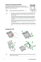
TPM connector (14-1 pin TPM) This connector supports a Trusted Platform Module (TPM) system, which can securely store keys, digital certificates, passwords and data. A TPM system also helps enhance network security, protects digital identities, and ensures platform integrity. Intel® B360 Serial ATA 6.0Gb/s connectors (7-pin SATA6G_1~6) These connectors connect to Serial ATA 6.0 Gb/s hard disk drives via Serial ATA 6.0 Gb/s signal cables. Chassis intrusion header (4-1 pin CHASSIS) This header is for a chassis-mounted intrusion detection sensor or switch Connect one end of the chassis intrusion sensor or switch cable to this header. The chassis intrusion sensor or switch sends a high-level signal to this header when a chassis component is removed or replaced. The signal is then generated as a chassis intrusion event. By default, the pin labeled "Chassis Signal" and "Ground" are shorted with a jumper cap. Remove the jumper caps only when you intend to use the chassis intrusion detection feature. System panel connector (10-1 pin F_PANEL) This connector supports several chassis-mounted functions. Speaker connector (4-pin SPEAKER) This 4-pin connector is for the chassis-mounted system warning speaker. The speaker allows you to hear system beeps and warnings. USB 2.0 connectors (10-1 pin USB914, USB1011) Connect the USB module cable to any of these connectors, then install the module to a slot opening at the back of the system chassis. These USB connectors comply with USB 2.0 specifications and support up to 480Mbps connection speed. RGB header (4-pin RGB_HEADER) This header is for RGB LED strips. The RGB header supports 5050 RGB multi-color LED strips (12V/G/R/B), with a maximum power rating of 3A (12V), and no longer than 3 m. Before you install or remove any component, ensure that the ATX power supply is switched off or the power cord is detached from the power supply. Failure to do so may cause severe damage to the motherboard, peripherals, or components. • Actual lighting and color will vary with LED strip. • If your LED strip does not light up, check if the RGB LED extension cable and the RGB LED strip is connected in the correct orientation, and the 12V connector is aligned with the 12V header on the motherboard. • The LED strip will only light up when the system is operating. • The LED strips are purchased separately. 1-3 ASUS PRIME B360M-A
-
 1
1 -
2
-
3
-
4
-
5
-
6
-
 7
7 -
 8
8 -
 9
9 -
 10
10 -
 11
11 -
 12
12 -
 13
13 -
 14
14 -
 15
15 -
 16
16 -
 17
17 -
18
-
19
-
20
-
21
-
22
-
23
-
24
-
25
-
26
-
27
-
28
 |
 |
