Asus PRIME H310I-PLUS R2.0 PRIME H310I-PLUS R20 Users Manual English - Page 10
LGA1151 CPU socket, DDR4 DIMM slots
 |
View all Asus PRIME H310I-PLUS R2.0 manuals
Add to My Manuals
Save this manual to your list of manuals |
Page 10 highlights
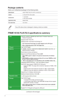
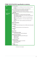
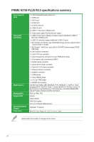
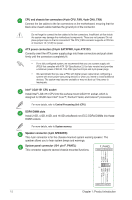
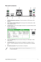
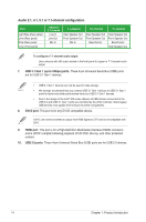
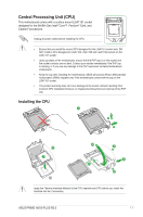
CPU and chassis fan connectors (4-pin CPU_FAN, 4-pin CHA_FAN) Connect the fan cables to the fan connectors on the motherboard, ensuring that the black wire of each cable matches the ground pin of the connector. Do not forget to connect the fan cables to the fan connectors. Insufficient air flow inside the system may damage the motherboard components. These are not jumpers! Do not place jumper caps on the fan connectors! The CPU_FAN connector supports a CPU fan of maximum 1A (12 W) fan power. ATX power connectors (24-pin EATXPWR, 4-pin ATX12V) Correctly orient the ATX power supply plugs into these connectors and push down firmly until the connectors completely fit. • For a fully configured system, we recommend that you use a power supply unit (PSU) that complies with ATX 12V Specification 2.0 (or later version) and provides a minimum power of 350 W. This PSU type has 24-pin and 4-pin power plugs. • We recommend that you use a PSU with higher power output when configuring a system with more power-consuming devices or when you intend to install additional devices. The system may become unstable or may not boot up if the power is inadequate. Intel® LGA1151 CPU socket Install Intel® LGA1151 CPU into this surface mount LGA1151 socket, which is designed for 9th/8th Gen Intel® Core™, Pentium® Gold, and Celeron® processors. For more details, refer to Central Processing Unit (CPU). DDR4 DIMM slots Install 2 GB, 4 GB, 8 GB, and 16 GB unbuffered non-ECC DDR4 DIMMs into these DIMM sockets. For more details, refer to System memory. Speaker connector (4-pin SPEAKER) This 4-pin connector is for the chassis-mounted system warning speaker. The speaker allows you to hear system beeps and warnings. System panel connector (10-1 pin F_PANEL) This connector supports several chassis-mounted functions. F_PANEL +PWR LED- PWR BTN P_LED+ P_LEDF_PWRBTN# GND PIN 1 HDD_LED+ HDD_LED- GND RSTCON#_PANEL (NC) +HDD_LED- RESET 1-2 Chapter 1: Product introduction
-
 1
1 -
2
-
3
-
4
-
 5
5 -
 6
6 -
 7
7 -
 8
8 -
 9
9 -
 10
10 -
 11
11 -
 12
12 -
 13
13 -
 14
14 -
 15
15 -
16
-
17
-
18
-
19
-
20
-
21
-
22
-
23
-
24
-
25
-
26
 |
 |
