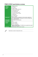
Asus PRIME Q270M-C/CSM User Guide - Page 10
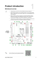
DDR4 DIMM slots, LGA1151 CPU socket
 |
View all Asus PRIME Q270M-C/CSM manuals
Add to My Manuals
Save this manual to your list of manuals |
Page 10 highlights
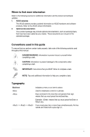
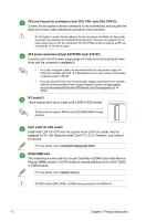
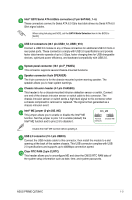
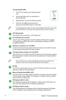
CPU and chassis fan connectors (4-pin CPU_FAN, 4-pin CHA_FAN1/2) Connect the fan cables to the fan connectors on the motherboard, ensuring that the black wire of each cable matches the ground pin of the connector. Do not forget to connect the fan cables to the fan connectors. Insufficient air flow inside the system may damage the motherboard components. These are not jumpers! Do not place jumper caps on the fan connectors! The CPU_FAN connector supports a CPU fan of maximum 1A (12 W) fan power. ATX power connectors (24-pin EATXPWR, 8-pin ATX12V) Correctly orient the ATX power supply plugs into these connectors and push down firmly until the connectors completely fit. • For a fully configured system, we recommend that you use a power supply unit (PSU) that complies with ATX 12 V Specification 2.0 (or later version) and provides a minimum power of 350 W. • If you are uncertain about the minimum power supply requirement for your system, refer to the Recommended Power Supply Wattage Calculator at http://support. asus.com/PowerSupplyCalculator/PSCalculator.aspx?SLanguage=en-us for details. M.2 socket 3 These sockets allow you to install an M.2 (NGFF) SSD module. M.2(SOCKET3) These sockets support M Key and 2242/2260/2280 storage devices. Intel® LGA1151 CPU socket Install Intel® LGA1151 CPU into this surface mount LGA1151 socket, which is designed for 7th / 6th Generation Intel® Core™ i7 / i5 / i3, Pentium®, and Celeron® processors. For more details, refer to Central Processing Unit (CPU). DDR4 DIMM slots This motherboard comes with four Double Data Rate 4 (DDR4) Dual Inline Memory Module (DIMM) sockets. A DDR4 module is notched differently from a DDR, DDR2, or DDR3 module. For more details, refer to System memory. DO NOT install a DDR, DDR2, or DDR3 memory module to the DDR4 slot. 1-2 Chapter 1: Product introduction
-
 1
1 -
2
-
3
-
4
-
 5
5 -
 6
6 -
 7
7 -
 8
8 -
 9
9 -
 10
10 -
 11
11 -
 12
12 -
 13
13 -
 14
14 -
 15
15 -
16
-
17
-
18
-
19
-
20
-
21
-
22
-
23
-
24
-
25
-
26
 |
 |