Asus PRIME Z270M-PLUS Motherboard Pin Definition.English - Page 14
Internal DC power connector 2-pin ATX19V, LCD panel monitor switch header 2-pin PANEL_SW
 |
View all Asus PRIME Z270M-PLUS manuals
Add to My Manuals
Save this manual to your list of manuals |
Page 14 highlights
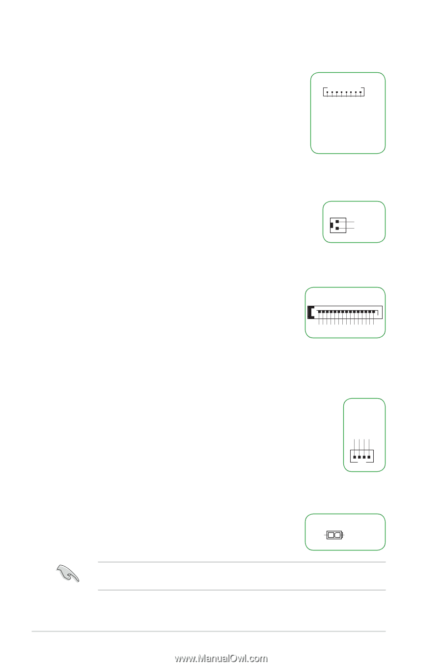
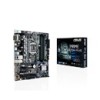
20. Flat panel display brightness connector (8-pin LCD_BLKT_PANEL) This connector is for the LCD panel backlight and brightness controls. It enables the LCD panel backlight, provides backlight control signals, and provides brightness control signals for the brightness button on the front panel. LCD_BLKT_PANEL PIN 1 BKLT_EN BKLT_PWM BKLT_PWR BKLT_PWR BKLT_GND/Brightness_GND BKLT_GND/Brightness_GND Brightness_up Brightness_Down 21. LCD panel monitor switch header (2-pin PANEL_SW) This 2-pin header is for connecting a monitor switch that can turn off the LCD panel display backlight. PANEL_SW GND MON_SW# PIN 1 22. SATA power connector (15-pin SATA_PWRCON) This connector is for the SATA power cable. The power cable plug is designed to fit this connector in only one orientation. Find the proper orientation and push down firmly until the connector completely fit. To provide power to your SATA device, connect the SATA power cable to this connector. +12V +12V +12V GND GND GND +5V +5V SATA_PWRCON PIN 1 +5V GND GND GND +3V +3V +3V 23. Internal stereo speaker header (4-pin INT_SPK) The internal mono speaker header allows connection to an internal, low-power speaker for basic system sound capability. The subsystem is capable of driving a speaker load of 4 Ohms at 3 Watts (rms). INT_SPK Front_L- Front_L+ Front_R+ Front_R- PIN 1 24. Internal DC power connector (2-pin ATX19V) This connector is for an ATX power supply. The plug from the power supply is designed to fit this connector in only one orientation. Find the proper orientation and push down firmly until the connector completely fits. ATX19V GND PIN 1 DC_JACK_IN This connector supports 12V and 19V by models. Refer to the specification sheet of the model for details. 1-14 Motherboard Pin Definition
-
 1
1 -
2
-
3
-
4
-
5
-
6
-
7
-
8
-
 9
9 -
 10
10 -
 11
11 -
 12
12 -
 13
13 -
 14
14 -
 15
15 -
 16
16 -
 17
17 -
 18
18
 |
 |