Asus PRIME Z270M-PLUS Motherboard Pin Definition.English - Page 5
Display panel VCC power selector VCC_PWR_SEL, LVDS panel/eDP selector 3-pin FPD_SEL - bios
 |
View all Asus PRIME Z270M-PLUS manuals
Add to My Manuals
Save this manual to your list of manuals |
Page 5 highlights
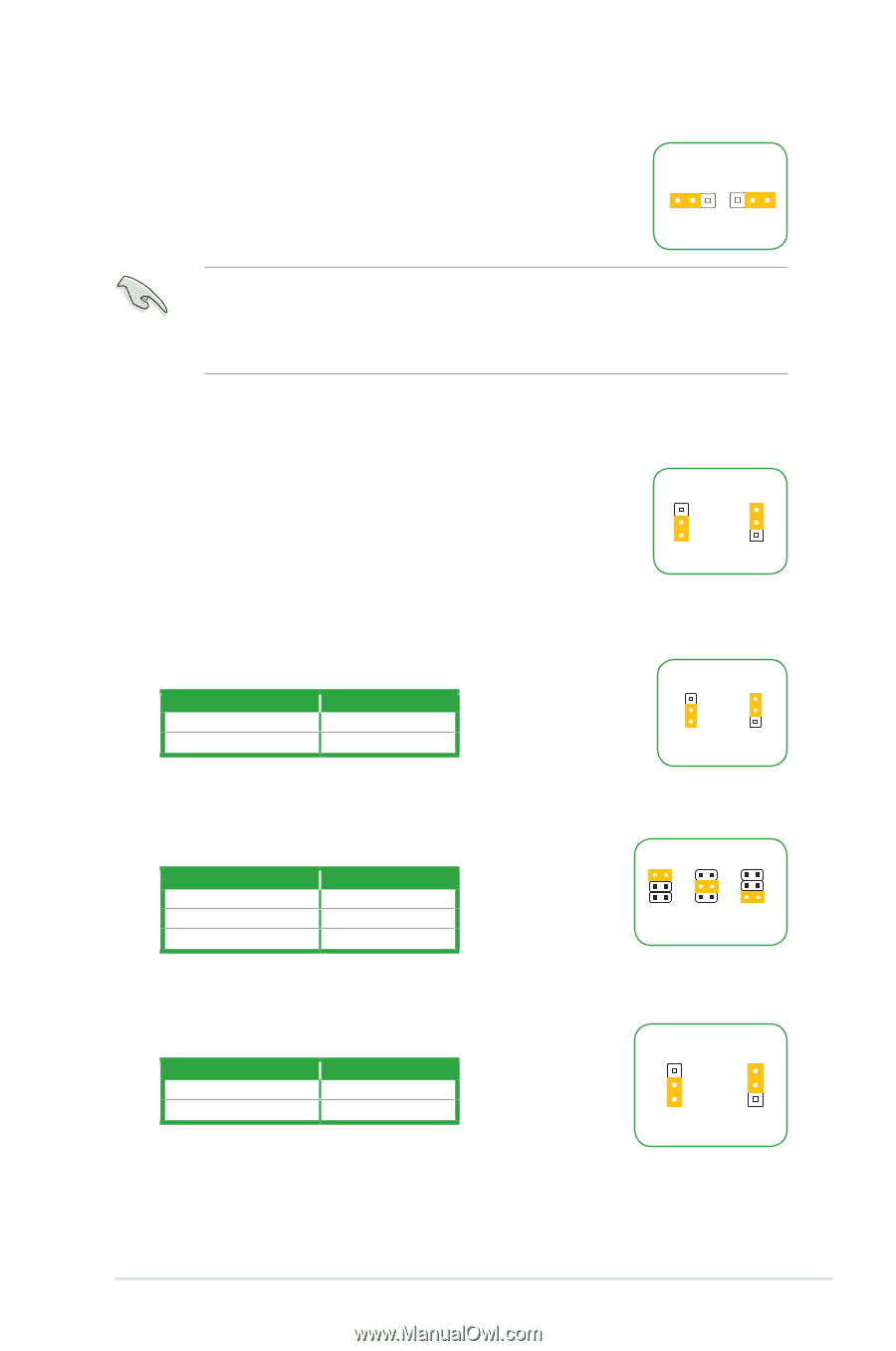
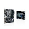
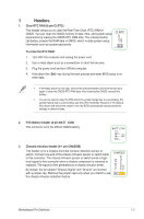
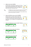
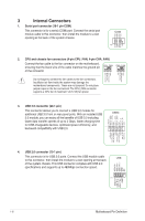
3. USB device wake-up (3-pin USBPWF) Set these jumpers to +5V to wake up the computer from S1 sleep mode (CPU stopped, DRAM refreshed, system running in low power USBPWF mode) using the connected USB devices. Set to +5VSB to wake 12 23 up from S3 and S4 sleep modes (no power to CPU, DRAM in slow +5V +5VSB refresh, power supply in reduced power mode). (Default) • The USB device wake-up feature requires a power supply that can provide 500mA on the +5VSB lead for each USB port; otherwise, the system would not power up. • The total current consumed must NOT exceed the power supply capability (+5VSB) whether under normal condition or in sleep mode. 4. Keyboard and USB device wake up (3-pin KB_USBPWB) This jumper allows you to enable or disable the keyboard and USB device wake-up feature. When you set this jumper to pins 2-3 (+5VSB), you can wake up the computer by pressing a key on the keyboard. This feature requires an ATX power supply that can supply at least 1A on the +5VSB lead, and a corresponding setting in the BIOS. 12 23 KB_USBPWB +5V +5VSB (Default) 5. Display panel backlight power selector (3-pin BLKT_PWR_SEL) BLKT_PWR_SEL 12 23 Pins 1-2 (Default) 2-3 Setting 12V 19V 12V 19V (Default) 6. Display panel VCC power selector (VCC_PWR_SEL) Pins 1 (Default) 2 3 Setting 3V 5V 12V 7. LVDS panel/eDP selector (3-pin FPD_SEL) Pins 1-2 (Default) 2-3 Setting LVDS eDP VCC_PWR_SEL 1 3V (Default) 2 5V 3 12V FPD_SEL 12 23 for LVDS (Default) for eDP Motherboard Pin Definition 1-5
-
 1
1 -
 2
2 -
 3
3 -
 4
4 -
 5
5 -
 6
6 -
 7
7 -
 8
8 -
 9
9 -
 10
10 -
 11
11 -
12
-
13
-
14
-
15
-
16
-
17
-
18
 |
 |