Asus Pro A620M-C-CSM Pro A620M-C Users Manual English - Page 13
COM Port header, COM Debug header, Front Panel Audio header, LPT header, System Management Bus header
 |
View all Asus Pro A620M-C-CSM manuals
Add to My Manuals
Save this manual to your list of manuals |
Page 13 highlights
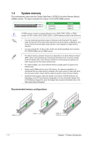
3. Plug the power cord and turn ON the computer. 4. Hold down the key during the boot process and enter BIOS setup to re-enter data. DO NOT short-circuit the pins except when clearing the RTC RAM. Short-circuiting or placing a jumper cap will cause system boot failure! If the steps above do not help, remove the onboard button cell battery and short the two pins again to clear the CMOS RTC RAM data. After clearing the CMOS, reinstall the button cell battery. RXD DTR DSR CTS 12. COM Port header The COM (Serial) Port header allows you to connect a COM port module. Connect the COM port module cable to this header, then install the module to a slot opening on the system chassis. The COM port module is purchased separately. COM PIN 1 DCD TXD GND RTS RI GND GND O_COM1_TXD1 13. COM Debug header This header allows connection to a COM Debug card. The COM Debug Card is purchased separately. COM_DEBUG PIN 1 SOUTC_P80 +3V 14. Front Panel Audio header The Front Panel Audio header is for a chassis-mounted front panel audio I/O module that supports HD Audio. Connect one end of the front panel audio I/O module cable to this header. We recommend that you connect a high-definition front panel audio module to this header to avail of the motherboard's high-definition audio capability. PORT1L PORT1R PORT2R SENSE_SEND PORT2L AGND NC SENSE1_RETUR SENSE2_RETUR AAFP PIN 1 HD-audio-compliant pin definition O_LPT_XAFD#_R O_LPT_ERROR#_R O_LPT_XINIT#_R O_LPT_XSLIN#_R GND GND GND GND GND GND GND GND 15. LPT header The LPT (Line Printing Terminal) header supports devices such as a printer. LPT standardizes as IEEE 1284, which is the parallel port interface LPT PIN 1 on IBM PC-compatible computers. O_LPT_XSTB#_R O_LPT_XPD0_R O_LPT_XPD1_R O_LPT_XPD2_R O_LPT_XPD3_R O_LPT_XPD4_R O_LPT_XPD5_R O_LPT_XPD6_R O_LPT_XPD7_R O_LPT_ACK#_R O_LPT_BUSY_R O_LPT_PE_R O_LPT_SLCT_R GND SMBUS_CLK 16. System Management Bus header The System Management Bus (SMBus) connector allows you to connect a SMBus device. This connector is generally used for communication with the system and power management-related tasks. SMBUS PIN 1 SMBUS_DATA Pro A620M-C 1-5
-
 1
1 -
2
-
3
-
4
-
5
-
6
-
7
-
 8
8 -
 9
9 -
 10
10 -
 11
11 -
 12
12 -
 13
13 -
 14
14 -
 15
15 -
 16
16 -
 17
17 -
 18
18 -
19
-
20
-
21
-
22
-
23
-
24
-
25
-
26
-
27
-
28
-
29
-
30
-
31
-
32
-
33
-
34
 |
 |
