Asus Pro A620M-C-CSM Pro A620M-C Users Manual English - Page 14
Power Button/Soft-off Button header PWR_BTN, Storage Device Activity LED header +HDD_LED
 |
View all Asus Pro A620M-C-CSM manuals
Add to My Manuals
Save this manual to your list of manuals |
Page 14 highlights
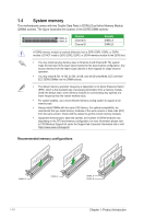
+5V GND GND Speaker Out 17. Speaker header The 4-pin header is for the chassis-mounted system warning speaker. The speaker allows you to hear system beeps and warnings. SPEAKER 18. SPI TPM header This header supports a Trusted Platform Module (TPM) system with a Serial Peripheral Interface (SPI), allowing you to securely store keys, digital certificates, passwords and data. A TPM system also enhances network security, protects digital identities, and ensures platform integrity. The TPM module is purchased separately. PIN 1 TPM T_SPI_MOSI T_SPI_CLK GND TPM_DETECT_L S_SPI_TPM_CS# S_SPI_TPM_IRQ# F_SPI_HOLD#_R T_SPI_MISO F_SPI_CZS0#_R F_SPI_PWR NC SPI_TPM_RST# SPI_TPM_PWR PIN 1 19. 10-1 pin System Panel header This header supports several chassis-mounted functions. • System Power LED header (+PWR_LED-) The 2-pin header allows you to connect the System Power LED. The System Power LED lights up when the system is connected to a power source, or when you turn on the system power, and blinks when the system is in sleep mode. PWR_LED+ PWR_LEDPWR GND F_PANEL +PWR_LED- PWR_BTN PIN 1 HDD_LED+ HDD_LED- Ground HWRST# (NC) • Storage Device Activity LED header (+HDD_LED-) The 2-pin header allows you to connect the Storage Device Activity +HDD_LED- RESET LED. The Storage Device Activity LED lights up or blinks when data is read from or written to the storage device or storage device add-on card. • Power Button/Soft-off Button header (PWR_BTN) The 2-pin header allows you to connect the system power button. Press the power button to power up the system, or put the system into sleep or soft-off mode (depending on the operating system settings). • Reset button header (RESET) The 2-pin header allows you to connect the chassis-mounted reset button. Press the reset button to reboot the system. 1-6 Chapter 1: Product Introduction
-
 1
1 -
2
-
3
-
4
-
5
-
6
-
7
-
8
-
 9
9 -
 10
10 -
 11
11 -
 12
12 -
 13
13 -
 14
14 -
 15
15 -
 16
16 -
 17
17 -
 18
18 -
 19
19 -
20
-
21
-
22
-
23
-
24
-
25
-
26
-
27
-
28
-
29
-
30
-
31
-
32
-
33
-
34
 |
 |
