Asus Pro H410T/CSM Pro H410T Users Manual English - Page 10
Layout contents, CPU socket, DDR4 DIMM slots, Fan headers, Internal DC power connector, M.2 slot key M
 |
View all Asus Pro H410T/CSM manuals
Add to My Manuals
Save this manual to your list of manuals |
Page 10 highlights
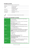
1.2.1 Layout contents 1. CPU socket The motherboard comes with a surface mount Intel® Socket LGA1200 designed for 10th Gen Intel® CoreTM, Pentium® Gold and Celeron® Processors. For more details, refer to Central Processing Unit (CPU). 2. DDR4 DIMM slots The motherboard comes with Dual Inline Memory Modules (DIMM) slots designed for DDR4 (Double Data Rate 4) memory modules. For more details, refer to System memory. GND FAN PWR FAN IN FAN PWM 3. Fan headers The Fan headers allow you to connect fans to cool the system. FAN PWM FAN IN FAN PWR GND 4. Internal DC power connector This connector is for a DC power supply. The plug from the power supply is designed to fit this connector in only one orientation. Find the proper orientation and push down firmly until the connector completely fits. This connector supports 12V and 19V by models. Refer to the specification sheet of the model for details. 5. M.2 slot (key M) The M.2 slot allows you to install a M.2 device such as a M.2 SSD module. M.2 slot (Key M), type 2260/2280 (supports PCIe 3.0 x4 & SATA modes) 6. SATA 6Gb/s ports The SATA 6Gb/s ports allow you to connect SATA devices such as optical disc drives and hard disk drives via a SATA cable. 7. USB 3.2 Gen 1 header The USB 3.2 Gen 1 header allows you to connect a USB 3.2 Gen 1 module for additional USB 3.2 Gen 1 ports. The USB 3.2 Gen 1 header provides data transfer speeds of up to 5 Gb/s. IntA_P2_D+ IntA_P2_DGND IntA_P2_SSTX+ IntA_P2_SSTXGND IntA_P2_SSRX+ IntA_P2_SSRXUSB3+5V The USB 3.2 Gen 1 module is purchased separately. PIN 1 GND IntA_P1_D+ IntA_P1_D- GND IntA_P1_SSTX+ IntA_P1_SSTX- GND IntA_P1_SSRX+ IntA_P1_SSRX- USB3+5V 1-2 Chapter 1: Product Introduction
-
 1
1 -
2
-
3
-
4
-
 5
5 -
 6
6 -
 7
7 -
 8
8 -
 9
9 -
 10
10 -
 11
11 -
 12
12 -
 13
13 -
 14
14 -
 15
15 -
16
-
17
-
18
-
19
-
20
-
21
-
22
-
23
-
24
-
25
-
26
-
27
-
28
 |
 |
