Asus Pro H510M-CT/CSM Pro H510M-CT Users Manual English - Page 14
COM Port header, COM Debug header, Front panel audio header, LPT header, M.2 slot Key E
 |
View all Asus Pro H510M-CT/CSM manuals
Add to My Manuals
Save this manual to your list of manuals |
Page 14 highlights
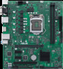
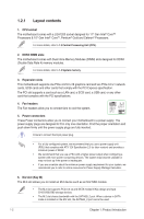
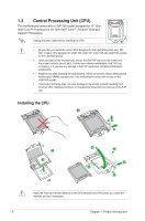
DCD TXD GND RTS RI RXD DTR DSR CTS 12. COM Port header This header is for a serial (COM) port. Connect the serial port module cable to this header, then install the module to a slot opening at the back of the system chassis. COM PIN 1 13. COM Debug header This header allows connection to a COM Debug card. The COM Debug Card is purchased separately. COM_DEBUG O_COM1_TXD1 GND GND +3V SOUTC_P80 PIN 1 AGND NC SENSE1_RETUR SENSE2_RETUR 14. Front panel audio header This header is for a chassis-mounted front panel audio I/O module that supports HD audio standard. Connect one end of the front panel audio I/O module cable to this header. PORT1 L PORT1 R PORT2 R SENSE_SEND PORT2 L • We recommend that you connect a high-definition front panel audio module to this header to avail of the motherboard's highdefinition audio capability. AAFP • If you want to connect a high-definition front panel audio module to this header, set the Front Panel Type item in the BIOS Setup to [HD Audio]. By default, this header is set to [HD Audio]. HD-audio-compliant pin definition O_LPT_XAFD#_R O_LPT_ERROR#_R O_LPT_XINIT#_R O_LPT_XSLIN#_R GND GND GND GND GND GND GND GND 15. LPT header The LPT (Line Printing Terminal) header supports devices such as a printer. LPT standardizes as IEEE 1284, which is the parallel port interface on IBM PC-compatible computers. PIN 1 16. M.2 slot (Key E) The M.2 Wi-Fi slot allows you to install an M.2 Wi-Fi module in CNVi mode. The M.2 Wi-Fi module is purchased separately. 17. System Management Bus header The System Management Bus (SMBus) header allows you to connect a SMBus device. This header is generally used for communication with the system and power management-related tasks. SMBUS SMBUS_CLK GND SMBUS_DATA PIN 1 O_LPT_XSTB#_R O_LPT_XPD0_R O_LPT_XPD1_R O_LPT_XPD2_R O_LPT_XPD3_R O_LPT_XPD4_R O_LPT_XPD5_R O_LPT_XPD6_R O_LPT_XPD7_R O_LPT_ACK#_R O_LPT_BUSY_R O_LPT_PE_R O_LPT_SLCT_R 1-4 Chapter 1: Product Introduction
-
 1
1 -
2
-
3
-
4
-
5
-
6
-
7
-
8
-
 9
9 -
 10
10 -
 11
11 -
 12
12 -
 13
13 -
 14
14 -
 15
15 -
 16
16 -
 17
17 -
 18
18 -
 19
19 -
20
-
21
-
22
-
23
-
24
-
25
-
26
-
27
-
28
-
29
-
30
-
31
-
32
 |
 |
