Asus Pro Q470M-C/CSM Pro Q470M-C Users Manual English - Page 12
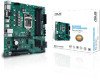
Layout contents, CPU socket, DDR4 DIMM slots, Expansion slots, Fan headers, Power connectors
 |
View all Asus Pro Q470M-C/CSM manuals
Add to My Manuals
Save this manual to your list of manuals |
Page 12 highlights
1.2.1 Layout contents 1. CPU socket The motherboard comes with a surface mount Intel® Socket LGA1200 designed for 10th Gen Intel® CoreTM, Pentium® Gold and Celeron® Processors. For more details, refer to Central Processing Unit (CPU). 2. DDR4 DIMM slots The motherboard comes with Dual Inline Memory Modules (DIMM) slots designed for DDR4 (Double Data Rate 4) memory modules. For more details, refer to System memory. 3. Expansion slots This motherboard supports one PCIe 3.0 x16 graphics card and one PCIe 3.0 x1 network card, SCSI card and other cards that comply with the PCI Express specification. The PCI slot supports cards such as a LAN card, SCSI card, USB card, and other cards that comply with PCI specifications. FAN PWM FAN IN FAN PWR GND 4. Fan headers The Fan headers allow you to connect fans to cool the system. FAN PWM FAN IN FAN PWR GND 5. Power connectors These Power connectors allow you to connect your motherboard to a power supply. The power supply plugs are designed to fit in only one orientation. Find the proper orientation and push down firmly until the power supply plugs are fully inserted. Ensure to connect the 8-pin power plug. • For a fully configured system, we recommend that you use a power supply unit (PSU) that complies with ATX 12V Specification 2.0 (or later version) and provides a minimum power of 350 W. • We recommend that you use a PSU with a higher power output when configuring a system with more power-consuming devices. The system may become unstable or may not boot up if the power is inadequate. • If you are uncertain about the minimum power supply requirement for your system, we recommend you to refer to online resources for Power Supply Wattage Calculator. 6. M.2 Slots (Key M) The M.2 slots allow you to install M.2 devices such as M.2 SSD modules. 1-2 Chapter 1: Product introduction
-
 1
1 -
2
-
3
-
4
-
5
-
6
-
 7
7 -
 8
8 -
 9
9 -
 10
10 -
 11
11 -
 12
12 -
 13
13 -
 14
14 -
 15
15 -
 16
16 -
 17
17 -
18
-
19
-
20
-
21
-
22
-
23
-
24
-
25
-
26
-
27
-
28
-
29
-
30
 |
 |
