Asus Pro Q470M-C/CSM Pro Q470M-C Users Manual English - Page 15
System power LED 2-pin +PWR_LED, Hard disk drive activity LED 2-pin +HDD_LED
 |
View all Asus Pro Q470M-C/CSM manuals
Add to My Manuals
Save this manual to your list of manuals |
Page 15 highlights
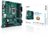
18. M.2 slot (Key E) This socket allows you to install an M.2 Wi-Fi device. The M.2 Wi-Fi module is purchased separately. 19. Mono out header This internal mono out header allows connection to an internal, low power speaker for basic system sound capability. You can connect a 3W speaker to this header. The subsystem is capable of driving a speaker load of 3 Watts RMS at 4 Ohms. MONO-OUT R_OUT+ R_OUT- PIN 1 +5V GND GND Speaker Out 20. Speaker header The 4-pin header is for the chassis-mounted system warning speaker. The speaker allows you to hear system beeps and warnings. SPEAKER 21. 10-1 pin System Panel header PIN 1 This header supports several chassis-mounted functions. • System power LED (2-pin +PWR_LED-) This 2-pin header is for the system power LED. Connect the chassis F_PANEL +PWR_LED- PWR_BTN PWR_LED+ PWR_LEDPWR GND power LED cable to this header. The system power LED lights up when you turn on the system power, and blinks when the system is in sleep mode. PIN 1 • Hard disk drive activity LED (2-pin +HDD_LED-) HDD_LED+ HDD_LED- Ground HWRST# (NC) This 2-pin header is for the HDD Activity LED. Connect the HDD Activity +HDD_LED- RESET LED cable to this header. The HDD LED lights up or flashes when data is read from or written to the HDD. • Power button/Soft-off button (2-pin PWR_BTN) This header is for the system power button. • Reset button (2-pin RESET) This 2-pin header is for the chassis-mounted reset button for system reboot without turning off the system power. ASUS Pro Q470M-C 1-5
-
 1
1 -
2
-
3
-
4
-
5
-
6
-
7
-
8
-
9
-
 10
10 -
 11
11 -
 12
12 -
 13
13 -
 14
14 -
 15
15 -
 16
16 -
 17
17 -
 18
18 -
 19
19 -
 20
20 -
21
-
22
-
23
-
24
-
25
-
26
-
27
-
28
-
29
-
30
 |
 |
