Asus ROG MAXIMUS Z790 EXTREME Users Manual English - Page 17
Layout contents, ROG MAXIMUS Z790 EXTREME
 |
View all Asus ROG MAXIMUS Z790 EXTREME manuals
Add to My Manuals
Save this manual to your list of manuals |
Page 17 highlights
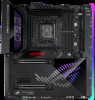
Chapter 1 Layout contents 1. CPU socket 2. DIMM slots 3. Expansion slots 4. Fan and Pump headers 5. Water Block header 6. Liquid Cooling System headers 7. Power connectors 8. M.2 Slot 9. DIMM.2 slot 10. SATA 6Gb/s port 11. Thunderbolt™ 4 port 12. USB 3.2 Gen 2x2 Type-C® Front Panel connector 13. USB 3.2 Gen 1 header 14. USB 2.0 header 15. Addressable Gen 2 header 16. Aura RGB header 17. BCLK buttons 18. BIOS Switch button 19. FlexKey button 20. Front Panel Audio header 21. LN2 Mode jumper 22. OSC Sense header 23. ProbeIt Measurement Points 24. ReTry button 25. RSVD switch and header 26. Safe Boot button 27. Slow Mode switch 28. Start button 29. System Panel header 30. Thermal Sensor header 31. V_Latch switch 32. Q-Code LED 33. Q-LEDs 34. BIOS LED 35. Storage Device Activity LED 36. 8-pin Power Plug LED Page 1-4 1-5 1-7 1-8 1-9 1-9 1-10 1-11 1-12 1-13 1-14 1-15 1-16 1-17 1-18 1-19 1-20 1-20 1-21 1-22 1-22 1-23 1-24 1-25 1-25 1-26 1-26 1-27 1-28 1-29 1-29 1-30 1-31 1+31 1-32 1-32 ROG MAXIMUS Z790 EXTREME 1-3
-
 1
1 -
2
-
3
-
4
-
5
-
6
-
7
-
8
-
9
-
10
-
11
-
 12
12 -
 13
13 -
 14
14 -
 15
15 -
 16
16 -
 17
17 -
 18
18 -
 19
19 -
 20
20 -
 21
21 -
 22
22 -
23
-
24
-
25
-
26
-
27
-
28
-
29
-
30
-
31
-
32
-
33
-
34
-
35
-
36
-
37
-
38
-
39
-
40
-
41
-
42
-
43
-
44
-
45
-
46
-
47
-
48
-
49
-
50
-
51
-
52
-
53
-
54
-
55
-
56
-
57
-
58
-
59
-
60
-
61
-
62
-
63
-
64
-
65
-
66
-
67
-
68
-
69
-
70
-
71
-
72
-
73
-
74
-
75
-
76
-
77
-
78
-
79
-
80
-
81
-
82
-
83
-
84
-
85
-
86
-
87
-
88
-
89
-
90
-
91
-
92
-
93
-
94
-
95
-
96
-
97
-
98
-
99
-
100
-
101
-
102
-
103
-
104
 |
 |
