Asus RS120-E4 User Guide - Page 64
LAN activity LED 2-pin LAN1_LED, LAN2_LED
 |
UPC - 610839641819
View all Asus RS120-E4 manuals
Add to My Manuals
Save this manual to your list of manuals |
Page 64 highlights
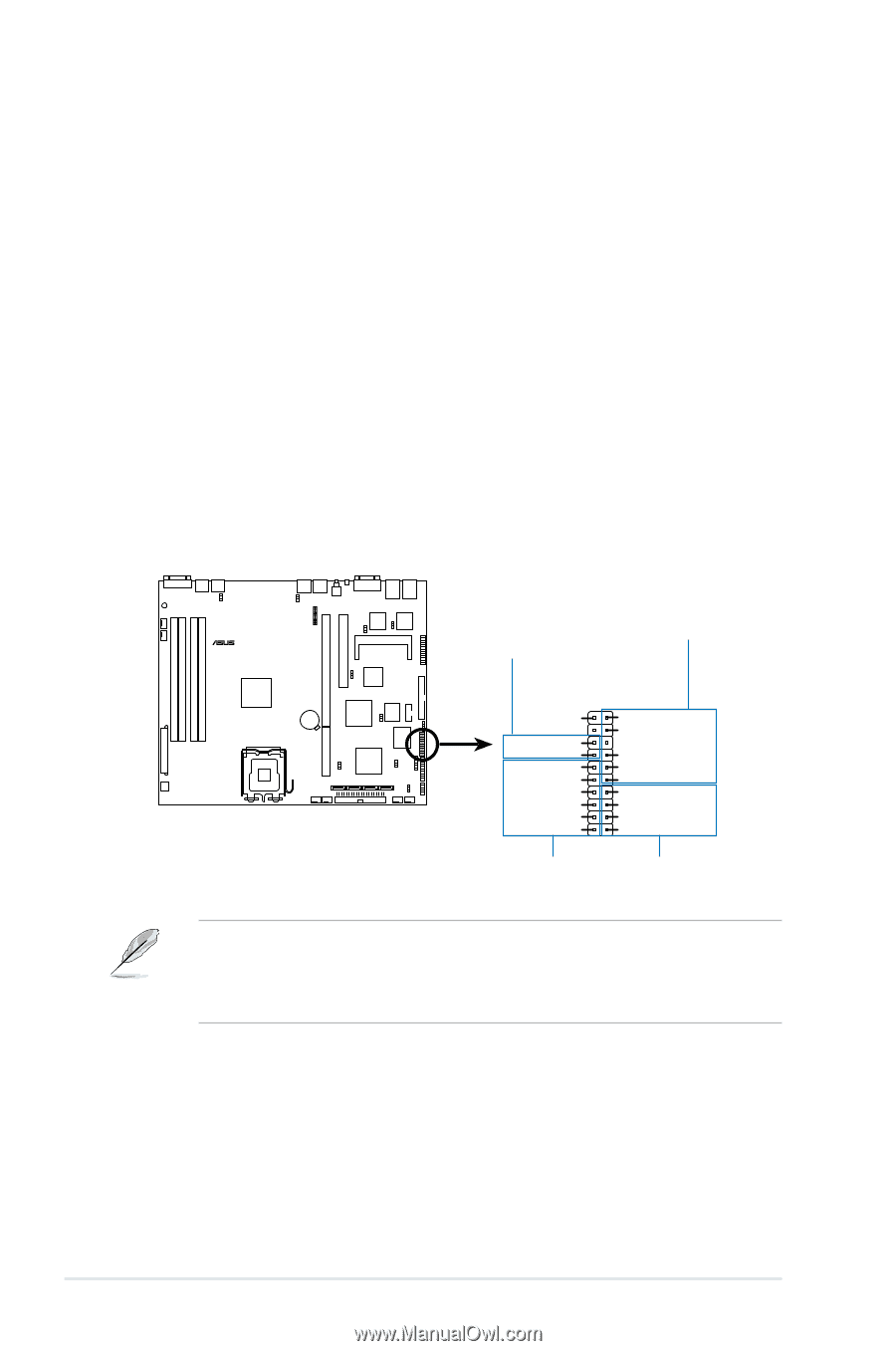
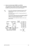
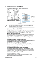
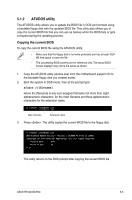
12. Auxiliary panel connector (20-pin AUX_PANEL1) This connector is for additional front panel features including front panel SMB, locator LED and switch, chassis intrusion, and LAN LEDs. • Front panel SMB (6-1 pin FPSMB) These leads connect the front panel SMBus cable. • LAN activity LED (2-pin LAN1_LED, LAN2_LED) These leads are for Gigabit LAN activity LEDs on the front panel. • Chassis intrusion (2-pin CHASSIS) These leads are for the intrusion detection feature for chassis with intrusion sensor or microswitch. When you remove any chassis component, the sensor triggers and sends a high-level signal to these leads to record a chassis intrusion event. • Locator LED (6-pin LOCATOR) These leads are for the locator switch and LED on the front panel. ® P5M2-R Chassis intrusion Front panel SMB P5M2-R.Auxiliary.panel.connector AUX_PANEL1 1 +5VSB CASEOPEN GND LOCATORLED1+ LOCATORLED1LOCATORBTN# GND LOCATORLED2LOCATORLED2+ NC I2C_4_CLK# GND I2C_4_DATA# +5VSB LAN1_LINKACTLEDLAN1_LINKACTLED+ LAN2_LINKACTLED+ LAN2_LINKACTLED- Locator LED and LAN activity LED switch By default, a cable plug (6x2, 12-pin) connects the AUX_PANEL1 to the front panel I/O board. The Pin1 on the cable plug is located at the top right corner and is marked by a triangle. Take note of the Pin1 when reconnecting the cable plug to prevent incorrect insertion. 4-16 Chapter 4: Motherboard information
-
 1
1 -
2
-
3
-
4
-
5
-
6
-
7
-
8
-
9
-
10
-
11
-
12
-
13
-
14
-
15
-
16
-
17
-
18
-
19
-
20
-
21
-
22
-
23
-
24
-
25
-
26
-
27
-
28
-
29
-
30
-
31
-
32
-
33
-
34
-
35
-
36
-
37
-
38
-
39
-
40
-
41
-
42
-
43
-
44
-
45
-
46
-
47
-
48
-
49
-
50
-
51
-
52
-
53
-
54
-
55
-
56
-
57
-
58
-
 59
59 -
 60
60 -
 61
61 -
 62
62 -
 63
63 -
 64
64 -
 65
65 -
 66
66 -
 67
67 -
 68
68 -
 69
69 -
70
-
71
-
72
-
73
-
74
-
75
-
76
-
77
-
78
-
79
-
80
-
81
-
82
-
83
-
84
-
85
-
86
-
87
-
88
-
89
-
90
-
91
-
92
-
93
-
94
-
95
-
96
-
97
-
98
-
99
-
100
-
101
-
102
-
103
-
104
-
105
-
106
-
107
-
108
-
109
-
110
-
111
-
112
-
113
-
114
-
115
-
116
-
117
-
118
-
119
-
120
-
121
-
122
-
123
-
124
-
125
-
126
-
127
-
128
-
129
-
130
-
131
-
132
-
133
-
134
-
135
-
136
-
137
-
138
-
139
-
140
-
141
-
142
-
143
-
144
-
145
-
146
-
147
-
148
-
149
-
150
-
151
-
152
-
153
-
154
-
155
-
156
-
157
-
158
-
159
-
160
-
161
-
162
-
163
-
164
-
165
-
166
-
167
-
168
-
169
-
170
-
171
-
172
-
173
-
174
 |
 |