Asus RS500-E6/PS4 Configuration Guide - Page 17
Installing ASUS PIKE RAID module
 |
UPC - 610839680191
View all Asus RS500-E6/PS4 manuals
Add to My Manuals
Save this manual to your list of manuals |
Page 17 highlights
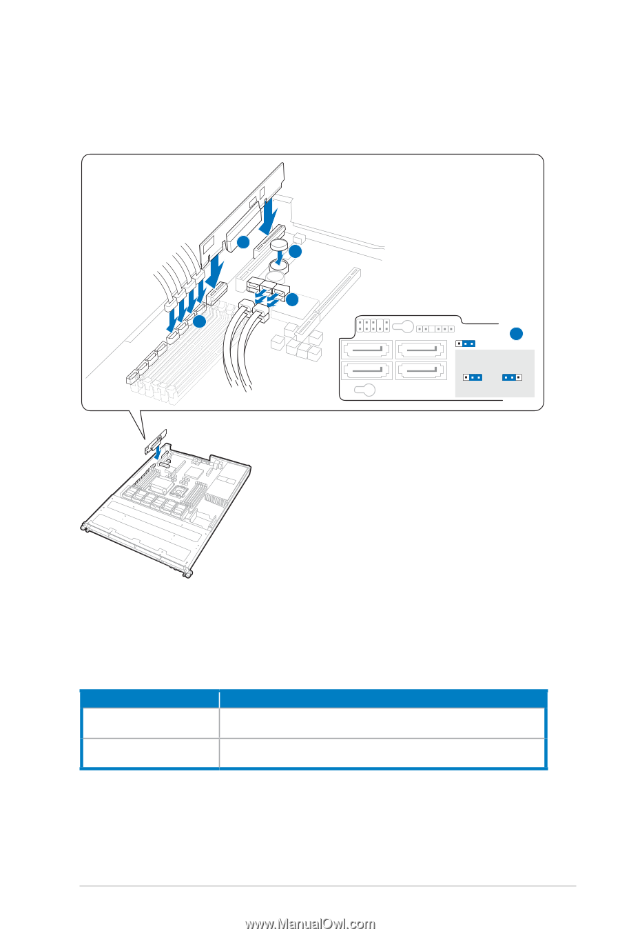
2.4 Installing ASUS PIKE RAID module The ASUS PIKE RAID module allows users to create RAID function from SAS hard disk drives connected to the SAS connectors on the motherboard. SAS1 1 SAS2 SAS3 SAS4 SATA4 SATA3 3 5 2 SSAATTAA21 SGPIO_SEL1 4 SGPIO_SEL1 21 32 On-Board Add-On Card 1. Insert the RAID card into the PIKE RAID card slot, ensuring that it is completely seated on the PIKE RAID card slot. 2. Remove the data cables connected to the SATA connectors on the motherboard. 3. Connect the data cables, by numerial order, to the SAS connectors labeled SAS1-4 (red) on the motherboard. 4. Set the SGPIO_SEL1 jumper on the backplane to pin 2-3 when connecting data cables to the SAS connectors on the motherboard. 5. Install the i Button*. * PIKE 1078 module won't function if the i Button is not installed. Order P/N 90-C1SCM0-00UAY00Z 90-C1SCN5-00UAY10Z Description ASUS PIKE 1064E 4-port SAS Module (Support Integrated RAID 0, 1, 1E) ASUS PIKE 1078 8-port SAS RAID Module (Support Hardware RAID 0, 1, 5, 6, 10) ASUS RS500-E6/PS4 2-7
-
 1
1 -
2
-
3
-
4
-
5
-
6
-
7
-
8
-
9
-
10
-
11
-
 12
12 -
 13
13 -
 14
14 -
 15
15 -
 16
16 -
 17
17 -
 18
18 -
 19
19 -
 20
20
 |
 |