Asus RS500A-E6 PS4 User Guide - Page 37
to the SATA connectors on
 |
View all Asus RS500A-E6 PS4 manuals
Add to My Manuals
Save this manual to your list of manuals |
Page 37 highlights
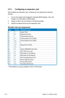
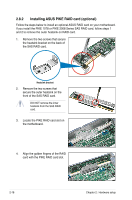
5. Insert the RAID card into the PIKE RAID card slot. Ensure that it is completely seated on the PIKE RAID card slot. 6. Remove the data cables connected to the SATA connectors on the motherboard. 7. Connect the data cables, by numerial order, to the SAS connectors labeled SAS1-4 (red) on the motherboard. 8. Remove the SGPIO cable from the SGPIO3 connector on the motherboard. ASUS RS500A-E6/PS4 2-19
-
 1
1 -
2
-
3
-
4
-
5
-
6
-
7
-
8
-
9
-
10
-
11
-
12
-
13
-
14
-
15
-
16
-
17
-
18
-
19
-
20
-
21
-
22
-
23
-
24
-
25
-
26
-
27
-
28
-
29
-
30
-
31
-
 32
32 -
 33
33 -
 34
34 -
 35
35 -
 36
36 -
 37
37 -
 38
38 -
 39
39 -
 40
40 -
 41
41 -
 42
42 -
43
-
44
-
45
-
46
-
47
-
48
-
49
-
50
-
51
-
52
-
53
-
54
-
55
-
56
-
57
-
58
-
59
-
60
-
61
-
62
-
63
-
64
-
65
-
66
-
67
-
68
-
69
-
70
-
71
-
72
-
73
-
74
-
75
-
76
-
77
-
78
-
79
-
80
-
81
-
82
-
83
-
84
-
85
-
86
-
87
-
88
-
89
-
90
-
91
-
92
-
93
-
94
-
95
-
96
-
97
-
98
-
99
-
100
-
101
-
102
-
103
-
104
-
105
-
106
-
107
-
108
-
109
-
110
-
111
-
112
-
113
-
114
-
115
-
116
-
117
-
118
-
119
-
120
-
121
-
122
-
123
-
124
-
125
-
126
-
127
-
128
-
129
-
130
-
131
-
132
-
133
-
134
-
135
-
136
-
137
-
138
-
139
-
140
-
141
-
142
 |
 |

2-19
ASUS RS500A-E6/PS4
7.
Connect the data cables, by
numerial order, to the SAS
connectors labeled SAS1-4 (red)
on the motherboard.
6.
Remove the data cables connected
to the SATA connectors on the
motherboard.
5.
Insert the RAID card into the PIKE
RAID card slot. Ensure that it is
completely seated on the PIKE
RAID card slot.
8.
Remove the SGPIO cable from
the SGPIO3 connector on the
motherboard.