Asus TS700-E4 User Manual - Page 89
activity LED 2-pin LAN1_LED, LAN2_LED
 |
UPC - 610839645985
View all Asus TS700-E4 manuals
Add to My Manuals
Save this manual to your list of manuals |
Page 89 highlights
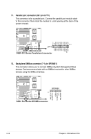
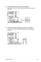
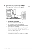
16. System panel auxiliary connector (20-2 pin AUX_PANEL1) This connector is for additional front panel features including front panel SMB, locator LED and switch, chassis intrusion, and LAN LEDs. 1 22 ® NC I2C_4_CLK# GND I2C_4_DATA# +5VSB LAN1_LINK LAN1_ACT LAN2_ACT LAN2_LINK AUX_PANEL1 PIN1 +5VSB CASEOPEN GND LOCATORLED1+ LOCATORLED1- LOCATORBTN# GND LOCATORLED2LOCATORLED2+ DSBF-D12 Series Auxiliary panel connector 3 454 1 Front panel SMB (6-1 pin FPSMB) These leads connect the front panel SMBus cable. 2 LAN activity LED (2-pin LAN1_LED, LAN2_LED) These leads are for Gigabit LAN activity LEDs on the front panel. 3 Chassis intrusion (2 pin CHASSIS) These leads are for the intrusion detection feature for chassis with intrusion sensor or microswitch. When you remove any chassis component, the sensor triggers and sends a high-level signal to these leads to record a chassis intrusion event. 4/5 Locator LED (6-pin LOCATOR) These leads are for the locator switch and LED on the front panel. ASUS TS700-E4/RX8 3-21
-
 1
1 -
2
-
3
-
4
-
5
-
6
-
7
-
8
-
9
-
10
-
11
-
12
-
13
-
14
-
15
-
16
-
17
-
18
-
19
-
20
-
21
-
22
-
23
-
24
-
25
-
26
-
27
-
28
-
29
-
30
-
31
-
32
-
33
-
34
-
35
-
36
-
37
-
38
-
39
-
40
-
41
-
42
-
43
-
44
-
45
-
46
-
47
-
48
-
49
-
50
-
51
-
52
-
53
-
54
-
55
-
56
-
57
-
58
-
59
-
60
-
61
-
62
-
63
-
64
-
65
-
66
-
67
-
68
-
69
-
70
-
71
-
72
-
73
-
74
-
75
-
76
-
77
-
78
-
79
-
80
-
81
-
82
-
83
-
 84
84 -
 85
85 -
 86
86 -
 87
87 -
 88
88 -
 89
89 -
 90
90 -
 91
91 -
 92
92 -
 93
93 -
 94
94 -
95
-
96
-
97
-
98
-
99
-
100
-
101
-
102
-
103
-
104
-
105
-
106
-
107
-
108
-
109
-
110
-
111
-
112
-
113
-
114
-
115
-
116
-
117
-
118
-
119
-
120
-
121
-
122
-
123
-
124
-
125
-
126
-
127
-
128
-
129
-
130
-
131
-
132
-
133
-
134
-
135
-
136
-
137
-
138
-
139
-
140
-
141
-
142
-
143
-
144
-
145
-
146
-
147
-
148
-
149
-
150
-
151
-
152
-
153
-
154
-
155
-
156
-
157
-
158
-
159
-
160
-
161
-
162
-
163
-
164
-
165
-
166
-
167
-
168
-
169
-
170
-
171
-
172
-
173
-
174
-
175
-
176
-
177
-
178
-
179
-
180
-
181
-
182
-
183
-
184
 |
 |
