Asus TUF GAMING B450M-PRO S Users Manual English - Page 12
Layout contents, CPU socket, DDR4 DIMM slots, Expansion slots, Hyper M.2 x16 series card configuration
 |
View all Asus TUF GAMING B450M-PRO S manuals
Add to My Manuals
Save this manual to your list of manuals |
Page 12 highlights
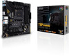
1.2.1 Layout contents 1. CPU socket The motherboard comes with an AMD Socket AM4 designed for 3rd/2nd/1st Gen AMD Ryzen™/2nd/1st Gen AMD Ryzen™ with Radeon™ Vega Graphics/ Athlon™ with Radeon™ Vega Graphics Processors. For more details, refer to Central Processing Unit (CPU). 2. DDR4 DIMM slots The motherboard comes with Dual Inline Memory Modules (DIMM) slots designed for DDR4 (Double Data Rate 4) memory modules. For more details, refer to System memory. 3. Expansion slots This motherboard supports two PCIe x16 graphics cards and one PCIe 3.0 x1 network card, SCSI card or other card that comply with the PCI Express specification. Please refer to the following table for the Hyper M.2 configuration. Hyper M.2 x16 series card configuration Slot PCIEX16_1 PCIe bifurcation settings in PCIe x16 slots with different Ryzen™ CPUs 3rd/2nd/1st Gen AMD Ryzen™ Processors (Support PCIe Gen 3 SSDs) Supported SSDs 4 • Hyper M.2 X16 series cards are sold separately. • When using 3rd/2nd/1st Gen AMD Ryzen™ Processors and a Hyper M.2 X16 series card with 4 M.2 SSDs, if you wish to connect a display, we suggest installing a VGA card to PCIe X16_2, which will run at x4. • Set PCIEX16_1 to [PCIe RAID Mode] under BIOS settings to enable the Hyper M.2 X16 series card. 4. Fan headers The Fan headers allow you to connect fans to cool the system. Header CPU_FAN CPU_OPT CHA_FAN1 CHA_FAN2 Max. Current 1A 1A 1A 1A Max. Power 12W 12W 12W 12W Default Speed Q-Fan Controlled Q-Fan Controlled Q-Fan Controlled Q-Fan Controlled Shared Control A A - GND FAN PWR FAN IN FAN PWM GND FAN PWR FAN IN FAN PWM 5. Power connectors These Power connectors allow you to connect your motherboard to a power supply. The power supply plugs are designed to fit in only one orientation. Find the proper orientation and push down firmly until the power supply plugs are fully inserted. Ensure to connect the 8-pin power plug. 1-2 Chapter 1: Product introduction
-
 1
1 -
2
-
3
-
4
-
5
-
6
-
 7
7 -
 8
8 -
 9
9 -
 10
10 -
 11
11 -
 12
12 -
 13
13 -
 14
14 -
 15
15 -
 16
16 -
 17
17 -
18
-
19
-
20
-
21
-
22
-
23
-
24
-
25
-
26
-
27
-
28
-
29
-
30
-
31
-
32
 |
 |
