Asus TXP4-X User Manual - Page 12
Iii. Installation
 |
View all Asus TXP4-X manuals
Add to My Manuals
Save this manual to your list of manuals |
Page 12 highlights
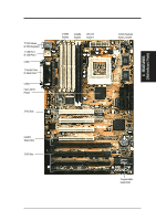
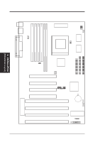
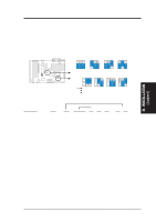
DIMM Socket 1 (64-bit, 168-pin module) DIMM Socket 2 (64-bit, 168-pin module) SIMM Socket 1 (32-bit, 72-pin module) SIMM Socket 2 (32-bit, 72-pin module) SIMM Socket 3 (32-bit, 72-pin module) SIMM Socket 4 (32-bit, 72-pin module) III. INSTALLATION (Motherboard Layout) III. INSTALLATION ASUS TXP4-X Motherboard Layout COM 1 PS/2 T: Mouse B: Keyboard USB T: USB 1 B: USB 2 FANPWR3 Board Power Input for ATX Power Supply CPU Voltage VID0 VID1 VID2 VID3 CPU Fan BUS Freq. BF0 BF1 BF2 256KB/512KB Onboard L2 Cache Parallel Port COM 2 Floppy Drives Secondary IDE Primary IDE Row 3 2 3 2 1 0 1 0 M/IO Multi-I/O (En/Dis) Row 3 2 1 0 PCI Slot 1 PCI Slot 2 PCI Slot 3 PCI Slot 4 ISA Slot 1 ISA Slot 2 ISA Slot 3 ISA Slot 4 CPU ZIF Socket 7 Intel 430TX PCIset BUS FREQ FS0 FS1 FS2 Intel PIIX4 R PCIset CR2032 3 Volt Lithium Cell BIOS Power FANPWR1 Flash ROM for BIOS Infrared Con. (IrDA) Panel Connections IDE LED RTC (Test/Clear) RTCLR Keyboard BIOS 12 ASUS TXP4-X User's Manual
-
 1
1 -
2
-
3
-
4
-
5
-
6
-
 7
7 -
 8
8 -
 9
9 -
 10
10 -
 11
11 -
 12
12 -
 13
13 -
 14
14 -
 15
15 -
 16
16 -
 17
17 -
18
-
19
-
20
-
21
-
22
-
23
-
24
-
25
-
26
-
27
-
28
-
29
-
30
-
31
-
32
-
33
-
34
-
35
-
36
-
37
-
38
-
39
-
40
-
41
-
42
-
43
-
44
-
45
-
46
-
47
-
48
-
49
-
50
-
51
-
52
-
53
-
54
-
55
-
56
-
57
-
58
-
59
-
60
-
61
-
62
 |
 |
