Asus V3-P5P43 Installation Manual - Page 10
Removing the bay covers and reinstalling the, front panel assembly and side cover
 |
View all Asus V3-P5P43 manuals
Add to My Manuals
Save this manual to your list of manuals |
Page 10 highlights
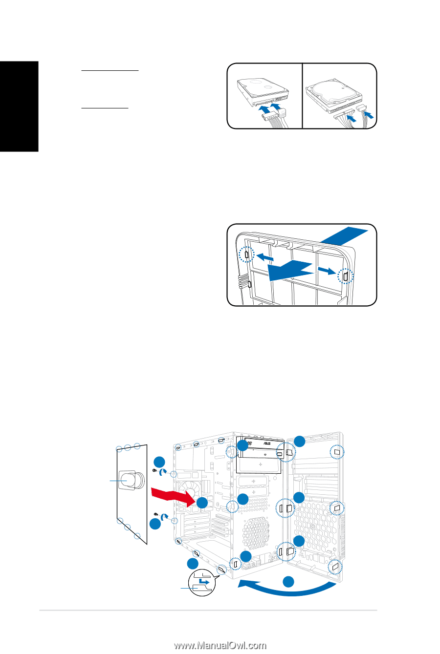
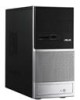
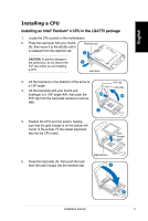
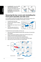
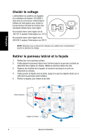
English 4. For SATA HDD: Connect the SATA SATA IDE signal and power plugs to the connectors at the back of the drive. For IDE HDD: Connect the IDE and power plugs to the connectors at the back of the drive. Removing the bay covers and reinstalling the front panel assembly and side cover If you installed an optical and/or floppy disk drive, remove the bay cover(s) on the front panel assembly before reinstalling it to the chassis. To do this: 1. Locate the bay cover locks. 2. Press the locks outward to release the bay cover. 3. Push the bay cover inward, then set it aside. 4. Follow the same instructions to remove the 3.5" drive bay cover. To reinstall the front panel assembly and side cover: 1. Insert the front panel assembly hinge-like tabs to the holes on the right side of the chassis. 2. Swing the front panel assembly to the left, then insert the hooks to the chassis until the front panel assembly fits in place. 3. Insert the six side cover hooks into the chassis tab holes . 4. Push the side cover to the direction of the front panel until it fits in place. 5. Secure the cover with two screws you removed earlier. Air duct 2 1 5 4 2 1 5 3 Chassis tab holes 1 2 2 10 Installation manual
-
 1
1 -
2
-
3
-
4
-
 5
5 -
 6
6 -
 7
7 -
 8
8 -
 9
9 -
 10
10 -
 11
11 -
 12
12 -
 13
13 -
 14
14 -
 15
15 -
16
-
17
-
18
-
19
-
20
-
21
-
22
-
23
-
24
-
25
-
26
-
27
-
28
-
29
-
30
-
31
-
32
-
33
-
34
-
35
-
36
-
37
-
38
-
39
-
40
-
41
-
42
-
43
-
44
-
45
-
46
-
47
-
48
-
49
-
50
-
51
-
52
-
53
-
54
-
55
-
56
-
57
-
58
-
59
-
60
-
61
-
62
-
63
-
64
-
65
-
66
-
67
-
68
-
69
-
70
-
71
-
72
-
73
-
74
-
75
-
76
-
77
-
78
-
79
-
80
-
81
-
82
-
83
-
84
-
85
-
86
-
87
-
88
-
89
-
90
-
91
-
92
-
93
-
94
-
95
-
96
-
97
-
98
-
99
-
100
 |
 |