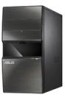
Asus V4-M3N8200 User Manual - Page 16
Audio 2, 4, 6, or 8-channel configuration
 |
View all Asus V4-M3N8200 manuals
Add to My Manuals
Save this manual to your list of manuals |
Page 16 highlights
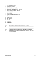
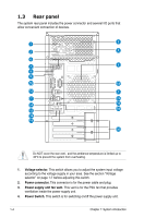
11. ESATA port. This port connects an external Serial ATA hard disk. 12. VGA port. This 15-pin port is for a VGA monitor or other VGA-compatible devices. 13. LAN (RJ-45) port. This port allows Gigabit connection to a Local Area Network (LAN) through a network hub. 14. Side Speaker Out port (gray). This port connects the sie speakers in an 8-channel audio configuration. 15. Microphone port (pink). This port connects a microphone. 16. Line Out port (lime). This port connects a headphone or a speaker. In 4-channel and 6-channel configuration, the function of this port becomes Front Speaker Out. 17. Line In port (light blue). This port connects the tape, CD, DVD player, or other audio sources. 18. Rear Speaker Out port (black). This port connects the rear speakers in a 4-channel, 6-channel, or 8-channel audio configuration. 19. Center / Subwoofer port (orange). This port connects the center / subwoofer speakers. Refer to the audio configuration table below for the function of the audio ports in 2, 4, 6, or 8-channel configuration. Audio 2, 4, 6, or 8-channel configuration Port Light Blue Headset 2-channel Line In 4-channel Surround Out 6-channel Line In 8-channel Line In Lime Pink Orange Black Gray Line Out Mic In - Front Speaker Out Front Speaker Out Front Speaker Out Mic In Mac In Mac In - Center/ Subwoofer Center/ Subwoofer Rear Speaker Out Rear Speaker Out Rear Speaker Out - - Side Speaker Out 20. Expansion slot covers. Remove these covers when installing expansion cards. 1-6 Chapter 1: System introduction
-
 1
1 -
2
-
3
-
4
-
5
-
6
-
7
-
8
-
9
-
10
-
 11
11 -
 12
12 -
 13
13 -
 14
14 -
 15
15 -
 16
16 -
 17
17 -
 18
18 -
 19
19 -
 20
20 -
 21
21 -
22
-
23
-
24
-
25
-
26
-
27
-
28
-
29
-
30
-
31
-
32
-
33
-
34
-
35
-
36
-
37
-
38
-
39
-
40
-
41
-
42
-
43
-
44
-
45
-
46
-
47
-
48
-
49
-
50
-
51
-
52
-
53
-
54
-
55
-
56
-
57
-
58
-
59
-
60
-
61
-
62
-
63
-
64
-
65
-
66
-
67
-
68
-
69
-
70
-
71
-
72
-
73
-
74
-
75
-
76
-
77
-
78
-
79
-
80
-
81
-
82
-
83
-
84
-
85
-
86
-
87
-
88
-
89
-
90
-
91
-
92
-
93
-
94
-
95
-
96
-
97
-
98
-
99
-
100
-
101
-
102
-
103
-
104
 |
 |
