Asus V8-P8H67E User Manual - Page 16
Voltage selector., Power connector., PS/2 keyboard port., USB 2.0 ports 1 ~ 4., HDMI port. - black
 |
View all Asus V8-P8H67E manuals
Add to My Manuals
Save this manual to your list of manuals |
Page 16 highlights
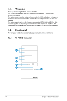
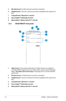
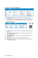
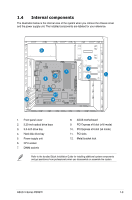
1. Voltage selector. This switch allows you to adjust the system input voltage according to the voltage supply in your area. See the section Voltage selector on page 1-8 before adjusting this switch. 2. Power connector. This connector is for the power cable and plug. 3. PS/2 keyboard port. This purple 6-pin connector is for a PS/2 keyboard. 4. USB 2.0 ports 1 ~ 4. These 4-pin Universal Serial Bus (USB) ports are available for connecting USB 2.0 devices. 5. HDMI port. This port is for a High-Definition Multimedia Interface (HDMI) connector, and is HDCP compliant allowing playback of HD DVD, Blu-Ray and other protected content. 6. DVI-D Out port. This port is for any DVI-D compatible device and is HDCP compliant allowing playback of HD DVD, Blu-Ray and other protected content. 7. USB 3.0 ports 1 ~ 2. These 4-pin Universal Serial Bus (USB) ports are available for connecting USB 3.0/2.0 devices. • Due to USB 3.0 controller limitation, USB 3.0 devices can only be used under Windows® OS environment and after the USB 3.0 driver installation. • USB 3.0 devices can only be used as data storage only. • We strongly recommend that you connect USB 3.0 devices to USB 3.0 ports for faster and better performance for your USB 3.0 devices. 8. Side Speaker Out port (gray). This port connects the side speakers in an 8-channel audio configuration. 9. Rear Speaker Out port (black). This port connects the rear speakers in a 4-channel, 6-channel, or 8-channel audio configuration. 10. Center/Subwoofer port (orange). This port connects the center/subwoofer speakers. 11. Microphone port (pink). This port connects a microphone. 12. Line Out port (lime). This port connects a headphone or a speaker. In 4-channel, 6- channel, and 8-channel configurations, the function of this port becomes Front Speaker Out. 13. Line In port (light blue). This port connects the tape, CD, DVD player, or other audio sources. Refer to the audio configuration table on the next page for the function of the audio ports in 2, 4, 6, or 8-channel configuration. 1-6 Chapter 1: System introduction
-
 1
1 -
2
-
3
-
4
-
5
-
6
-
7
-
8
-
9
-
10
-
 11
11 -
 12
12 -
 13
13 -
 14
14 -
 15
15 -
 16
16 -
 17
17 -
 18
18 -
 19
19 -
 20
20 -
 21
21 -
22
-
23
-
24
-
25
-
26
-
27
-
28
-
29
-
30
-
31
-
32
-
33
-
34
-
35
-
36
-
37
-
38
-
39
-
40
-
41
-
42
-
43
-
44
-
45
-
46
-
47
-
48
-
49
-
50
-
51
-
52
-
53
-
54
-
55
-
56
-
57
-
58
-
59
-
60
-
61
-
62
-
63
-
64
-
65
-
66
-
67
-
68
-
69
-
70
-
71
-
72
-
73
-
74
-
75
-
76
-
77
-
78
-
79
 |
 |
