Asus Z170-AR User Guide - Page 78
VRM Spread Spectrum [Disabled], Fixed VCCGT Switching FrequencyKHz [300]
 |
View all Asus Z170-AR manuals
Add to My Manuals
Save this manual to your list of manuals |
Page 78 highlights
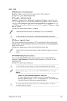
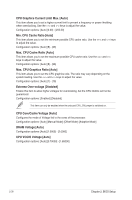
The following item appears only when the CPU VRM Switching Frequency is set to [Auto]. VRM Spread Spectrum [Disabled] This item allows to enhance the system stability. Configuration options: [Disabled] [Enabled] CPU Power Duty Control [T.Probe] DIGI + VRM Duty Control adjusts the current of every VRM phase and the thermal conditions of every phase component. [T. Probe] Select to set the VRM thermal balance mode. [Extreme] Select to set the VRM current balance mode. DO NOT remove the thermal module. The thermal conditions should be monitored. CPU Power Phase Control [Auto] This item allows you to set the power phase control of the CPU. Configuration options: [Auto] [Standard] [Optimized] [Extreme] DO NOT remove the thermal module when setting this item to [Extreme]. The thermal conditions should be monitored. CPU Graphic Load-line Calibration [Auto] Load-line is defined by IntelR specification and affects CPU power voltage. The CPU working voltage decreases proportionally to CPU loading. Higher load-line calibration could get higher voltage and good overclocking performance, but increases the CPU and VRM thermal conditions. Select from levels 1 to 7 to adjust the CPU power voltage from 0% to 100%. [Auto] [Level 1] - [Level 7] CPU Graphics Current Capability [Auto] The GT current capability adjusts the total power range for GT overclocking. A higher value provides a wider total power range and extends the overclocking frequency range simultaneously. Configuration options: [Auto] [100%] [110%] [120%] [130%] CPU Graphics [Auto] The switching frequency will affect the GT transient response speed and the component thermal production. Select the manual mode to configure a higher frequency to get a quicker transient response speed. [Auto] [Manual] The following item appears only when you set the CPU Graphics to [Manual]. Fixed VCCGT Switching Frequency(KHz) [300] This item allows you to set a higher frequency for a quicker transient response speed. Use the or to adjust the value. The values range from 300 KHz to 600 KHz with an interval of 50 KHz. 2-26 Chapter 2: BIOS Setup
-
 1
1 -
2
-
3
-
4
-
5
-
6
-
7
-
8
-
9
-
10
-
11
-
12
-
13
-
14
-
15
-
16
-
17
-
18
-
19
-
20
-
21
-
22
-
23
-
24
-
25
-
26
-
27
-
28
-
29
-
30
-
31
-
32
-
33
-
34
-
35
-
36
-
37
-
38
-
39
-
40
-
41
-
42
-
43
-
44
-
45
-
46
-
47
-
48
-
49
-
50
-
51
-
52
-
53
-
54
-
55
-
56
-
57
-
58
-
59
-
60
-
61
-
62
-
63
-
64
-
65
-
66
-
67
-
68
-
69
-
70
-
71
-
72
-
 73
73 -
 74
74 -
 75
75 -
 76
76 -
 77
77 -
 78
78 -
 79
79 -
 80
80 -
 81
81 -
 82
82 -
 83
83 -
84
-
85
-
86
-
87
-
88
-
89
-
90
-
91
-
92
-
93
-
94
-
95
-
96
-
97
-
98
-
99
-
100
-
101
-
102
-
103
-
104
-
105
-
106
-
107
-
108
-
109
-
110
-
111
-
112
-
113
-
114
-
115
-
116
-
117
-
118
-
119
-
120
-
121
-
122
-
123
-
124
-
125
-
126
-
127
-
128
-
129
-
130
 |
 |
