Asus p4p800s P4P800S user's manual English version E1398 - Page 38
ATX Power Switch/Soft-off Switch Lead 2-pin PWR light green
 |
View all Asus p4p800s manuals
Add to My Manuals
Save this manual to your list of manuals |
Page 38 highlights
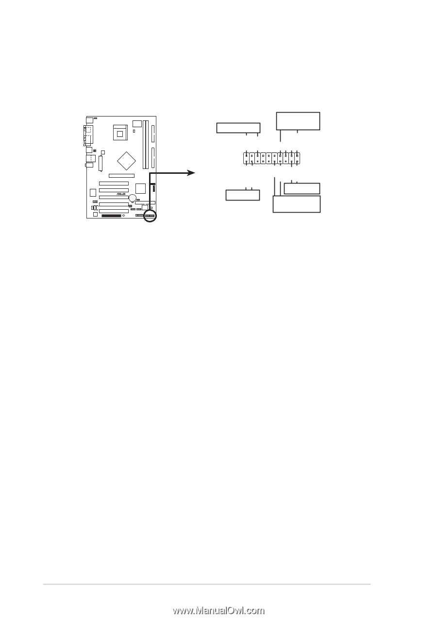
11. System panel connector (20 pin PANEL1) This connector accommodates several system front panel functions. Each group of connector pins match the color of the wire connectors for easier location and identification. Power LED Speaker Connector PLED+ PLED+5V Ground Ground Speaker IDE_LED+ IDE_LED- PWR Ground Reset Ground P4P800S Reset SW ® IDE_LED ATX Power Switch* * Requires an ATX power supply. P4P800S System Panel Connector • System Power LED Lead (3-1 pin PLED (green)) This 3-1 pin connector connects to the system power LED. The LED lights up when you turn on the system power, and blinks when the system is in sleep mode. • System Warning Speaker Lead (4-pin SPKR (orange)) This 4-pin connector connects to the case-mounted speaker and allows you to hear system beeps and warnings. • Reset Switch Lead (2-pin RESET (blue)) This 2-pin connector connects to the case-mounted reset switch for rebooting the system without turning off the system power. • ATX Power Switch/Soft-off Switch Lead (2-pin PWR (light green)) This connector connects a switch that controls the system power. Pressing the power switch turns the system between ON and SLEEP, or ON and SOFT OFF, depending on the BIOS or OS settings. Pressing the power switch while in the ON mode for more than 4 seconds turns the system OFF. • Hard Disk Activity Lead (2-pin IDE_LED (red)) This connector supplies power to the hard disk activity LED. The read or write activities of any device connected to the primary or secondary IDE connector cause this LED to light up. 1-28 Chapter 1: Product introduction
-
 1
1 -
2
-
3
-
4
-
5
-
6
-
7
-
8
-
9
-
10
-
11
-
12
-
13
-
14
-
15
-
16
-
17
-
18
-
19
-
20
-
21
-
22
-
23
-
24
-
25
-
26
-
27
-
28
-
29
-
30
-
31
-
32
-
 33
33 -
 34
34 -
 35
35 -
 36
36 -
 37
37 -
 38
38 -
 39
39 -
 40
40 -
 41
41 -
 42
42 -
 43
43 -
44
-
45
-
46
-
47
-
48
-
49
-
50
-
51
-
52
-
53
-
54
-
55
-
56
-
57
-
58
-
59
-
60
-
61
-
62
-
63
-
64
-
65
-
66
-
67
-
68
-
69
-
70
-
71
-
72
-
73
-
74
-
75
-
76
-
77
-
78
-
79
-
80
-
81
-
82
 |
 |