Asus p4p800vm P4P800-VM user's manual English version E1338 - Page 38
Digital audio connector 4-1 pin SPDIF1, System panel connector 20-pin PANEL1, System Power LED Lead - front panel
 |
View all Asus p4p800vm manuals
Add to My Manuals
Save this manual to your list of manuals |
Page 38 highlights
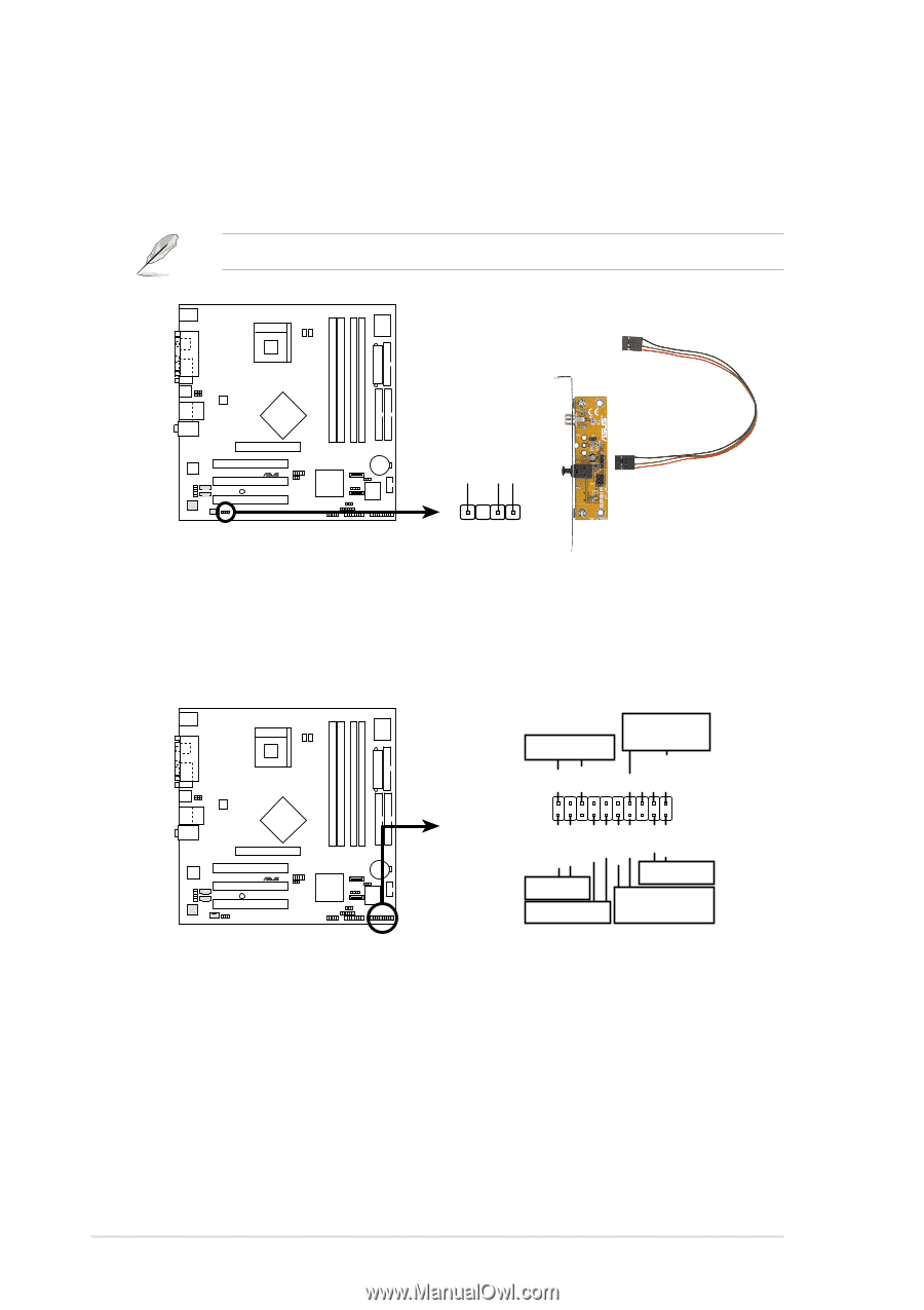
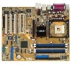
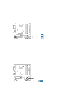
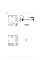
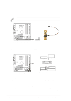
14. Digital audio connector (4-1 pin SPDIF1) This connector is for a S/PDIF audio module that allows digital instead of analog sound output. Connect one end of the audio cable to the S/PDIF Out connector on the motherboard, and the other end to the S/PDIF module. The S/PDIF module is purchased separately. P4P800-VM +5V SPDIFOUT GND SPDIF1 ® P4P800-VM Digital Audio Connector 15. System panel connector (20-pin PANEL1) This connector accommodates several system front panel functions. Speaker Power LED Connector +5 V PLED +5V Ground Ground Speaker P4P800-VM HD_LED+ HD_LEDExtSMI# Ground PWRBIN Ground Reset Ground Reset SW ® IDELED ATX Power SMI Lead Switch* P4P800-VM System Panel Connectors * Requires an ATX power supply. • System Power LED Lead (3-1 pin PLED) This 3-1 pin connector connects to the system power LED. The LED lights up when you turn on the system power, and blinks when the system is in sleep mode. • Hard disk activity LED (2-pin IDELED) This 2-pin connector supplies power to the hard disk activity LED. The read and write activities of any device connected to the primary or secondary IDE connector cause this LED to light up. 1-28 Chapter 1: Product introduction
-
 1
1 -
2
-
3
-
4
-
5
-
6
-
7
-
8
-
9
-
10
-
11
-
12
-
13
-
14
-
15
-
16
-
17
-
18
-
19
-
20
-
21
-
22
-
23
-
24
-
25
-
26
-
27
-
28
-
29
-
30
-
31
-
32
-
 33
33 -
 34
34 -
 35
35 -
 36
36 -
 37
37 -
 38
38 -
 39
39 -
 40
40 -
 41
41 -
 42
42 -
 43
43 -
44
-
45
-
46
-
47
-
48
-
49
-
50
-
51
-
52
-
53
-
54
-
55
-
56
-
57
-
58
-
59
-
60
-
61
-
62
-
63
-
64
-
65
-
66
-
67
-
68
-
69
-
70
-
71
-
72
-
73
-
74
-
75
-
76
-
77
-
78
-
79
-
80
 |
 |