Audiovox VBP5000 Owners Manual - Page 18
G. Controls, Indicators, And Connectors, - remote
 |
UPC - 044476012518
View all Audiovox VBP5000 manuals
Add to My Manuals
Save this manual to your list of manuals |
Page 18 highlights
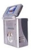
G. CONTROLS, INDICATORS, AND CONNECTORS 1. UNIT VIEW (Refer to Figure 16) MONITOR RIGHT SIDE 1) Brightness UP/DOWN Thumbwheel 2) Volume UP/DOWN Thumbwheel 3) Headphone Input # 2 4) Headphone Input # 1 MAIN UNIT 5) REMOTE CONTROL SENSOR 6) MAIN POWER 7) VCP STOP/EJECT Button 8) VCP REWIND Button 9) VCP PLAY Button 10) VCP FAST FORWARD Button 11) DVD/AV and VCP SELECT Switch 12) DVD OPEN Button 13) DVD STOP Button 14) DVD PREVIOUS Button 15) DVD PLAY Button 16) DVD NEXT Button MONITOR LEFT SIDE 17) POWER ON/OFF BUTTON (Monitor) 18) RIGHT AUDIO IN (Monitor) 19) LEFT AUDIO IN (Monitor) 20) VIDEO IN (Monitor) 21) MONITOR JACK (Input) 22) DC 12V INPUT (Monitor) MAIN UNIT BOTTOM 23) DVD/AV OUTPUT 24) MONITOR PORT #1 (Output) 25) VCP A/V OUTPUT 26) MONITOR PORT #2 (Output) 27) DC 12V INPUT 28) A/V INPUT Right Side Front Left Side Bottom Right Figure 16 15
-
 1
1 -
2
-
3
-
4
-
5
-
6
-
7
-
8
-
9
-
10
-
11
-
12
-
 13
13 -
 14
14 -
 15
15 -
 16
16 -
 17
17 -
 18
18 -
 19
19 -
 20
20 -
 21
21 -
 22
22 -
 23
23 -
24
-
25
-
26
-
27
-
28
-
29
-
30
-
31
-
32
-
33
-
34
-
35
-
36
-
37
-
38
-
39
-
40
-
41
-
42
-
43
-
44
 |
 |
