Behringer 110 VCO/VCF/VCA Quick Start Guide - Page 1
Behringer 110 VCO/VCF/VCA Manual
 |
View all Behringer 110 VCO/VCF/VCA manuals
Add to My Manuals
Save this manual to your list of manuals |
Page 1 highlights
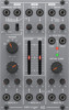
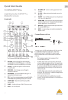
Quick Start Guide 110 VCO/VCF/VCA Legendary Analog VCO/VCF/VCA Module for Eurorack Controls (1) (2) (9) (3) (4) (5) (6) (7) (9) VCF/VCA SIG IN - Connect incoming signals via 3.5 mm TS cables. (10) SIG LEVEL - Adjust the level of the signals connected to the inputs. (11) VCA OUT - Sends the VCA signal via 3.5 mm TS cable with either high or low signal levels. (12) INITIAL GAIN - Adjusts the initial gain level when there is no control voltage present. The adjacent LEDs will light to indicate signal (green) and overload (red). (13) MOD LEVEL - Adjusts the level of the signal connected to the associated MOD IN jack. (14) MOD IN - Accepts voltages that control or modulate the VCO, VCF or VCA. (10) Power Connection (11) (8) (12) The module comes with the required power cable for connecting (13) to a standard Eurorack power supply system. Follow these steps to connect power to the module. It is easier to make these connections before the module has been mounted into (14) a rack case. 1. Turn the power supply or rack case power off and disconnect the power cable. (1) PW MOD - Accepts a voltage from another module to control the pulse width. When a jack is inserted the MOD MANUAL control acts as a MOD input level control. 2. Insert the 16-pin connector on the power cable into the socket on the power supply or rack case. The connector has a tab that will align with the gap in the socket, so it cannot (2) VCO OUT - Send the VCO signal to another source via be inserted incorrectly. If the power supply does not have 3.5 mm TS cable. a keyed socket, be sure to orient pin 1 (-12 V) with the red stripe on the cable. (3) WAVEFORM - Select triangle, sawtooth or pulse waveforms for the VCO. 3. Insert the 10-pin connector into the socket on the back of the module. The connector has a tab that will align with the (4) MOD MANUAL - Sets the ratio between the upper and socket for correct orientation. lower portions of the pulse wave. 4. After both ends of the power cable have been securely (5) RES - Boosts the resonance frequencies selected with the attached, you may mount the module in a case and turn on CUTOFF FREQ slider, potentially causing VCF oscillation. the power supply. (6) CUTOFF FREQ - Adjusts the cutoff frequency of the low-pass filter. (7) RANGE - Sets the pitch range of the VCO in octave steps. (8) PITCH - Fine tunes the pitch. V 1.0
-
 1
1 -
 2
2 -
 3
3
 |
 |