Behringer 2600 GRAY MEANIE Quick Start Guide - Page 8
Ring Modulator Noise Generator Voltage Processor Sample & Hold/ - difference
 |
View all Behringer 2600 GRAY MEANIE manuals
Add to My Manuals
Save this manual to your list of manuals |
Page 8 highlights
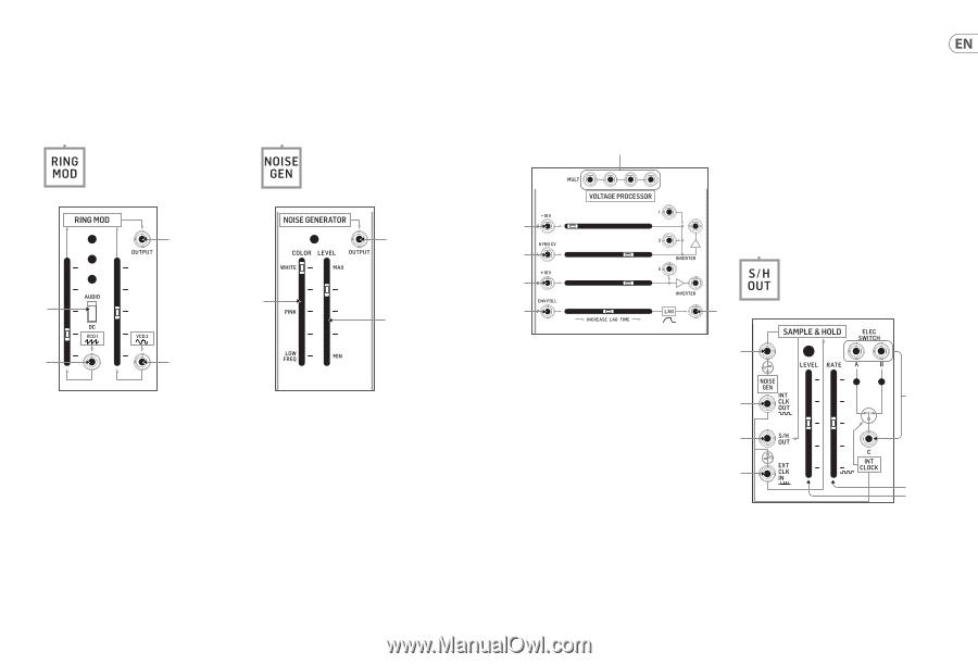
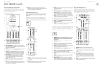
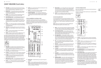
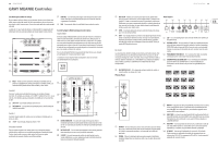
14 GRAY MEANIE GRAY MEANIE Controls Ring Modulator Section The Ring Modulator is a voltage multiplier that combines two input signals to produce a variety of exotic timbres. By default, the two pre-wired signals come into the circuit from VCO1 (sawtooth) and VCO2 (sine). The Ring Modulator output is available as a pre-wired connection wherever you see this label: Noise Generator Section The Noise Generator produces a noise signal that can be adjusted between white, pink and low frequency types of noise, each of which has distinct characteristics and can then be processed in other sections of the synth to design sounds. The Noise Generator output is available as a pre-wired connection wherever you see this label: (74) (77) (75) (73) (76) (71) (72) (71) VCO 1 - This input jack allows you to route in an external signal for blending with the pre-wired VCO1 sawtooth signal. The overall gain for this combined signal is adjusted by the adjacent slider. (72) VCO 2 - This input jack allows you to route in an external signal for blending with the pre-wired VCO2 sine wave signal. The overall gain for this combined signal is adjusted by the adjacent slider. (73) AUDIO/DC - Use this switch to optimize the VCO1 signal path for audio (AUDIO) or control voltage (DC) signals. (74) RING MOD OUTPUT - This jack can be used to send out the final, summed Ring Modulator for use elsewhere where a pre-wired connection is not available. (75) COLOR - Use this slider to move between white noise (WHITE), pink noise (PINK) and low frequency noise (LOW FREQ). (76) LEVEL - This slider controls the overall attenuation of the noise signal prior to output. (77) NOISE GENERATOR OUTPUT - Use this output to send the final noise signal out for use in the synth where a pre-wired connection is not available. Quick Start Guide 15 Voltage Processor Section The Voltage Processor offers three different processors for both audio and control voltage signals. Two of the processors are for mixing and inverting signals, while the third processor applies a variable lag to the signal. The Voltage Processor's output is not available elsewhere in the synth as a prewired signal, and so requires cables. (78) (79) (80) (82) ENV FOLL - This input can accept both control voltages and audio signals but is optimized to process the Envelope Follower output signal. (83) LAG - This jack sends out the final signal from the Lag Processor. Sample & Hold/Electronic Switch Section Sample & Hold The Sample & Hold circuit takes an input signal and converts that signal into a stepped output by taking samples of the input signal at set intervals. For example, a smooth sine wave input will appear at the output as a squared-off, approximate version of the original smooth waveform. This stepped waveform can then be sent other areas of the synthesizer to create exotic sounds and textures. This Sample & Hold circuit has an internal clock generator and a pre-wired connection from the Noise Generator circuit. The Sample & Hold circuit's output is available as a pre-wired connection wherever you see this label: (81) (82) (83) (84) (78) MULT - These linked parallel connections can be used as a patch bay to duplicate and combine signals. The MULT connections can function as both inputs and outputs. Inverter 1 Inverter 1 accepts four different inputs, which are summed and then inverted. For example, a +10 V input to INPUT 1 will leave Inverter 1 with a value of -10 V, while an audio signal will be output with the phase reversed 180°. (79) -10 V - This input attenuates the input signal by 10 V. (80) KYBD CV - This input is optimized for control voltage signal from a keyboard. Inverter 2 Inverter 2 can accept two signals, which are then summed and inverted for output. (81) +10 V - This inputs boosts the input signal by +10 V. Lag Processor The Lag Processor responds to sudden changes in input voltage and slows down those changes by an amount controlled by the slider. For audio signals, the Lag Processor will cut off treble frequencies by increasing amounts, similar to a lowpass filter. (90) (85) (86) (87) (89) (88) (84) NOISE GENERATOR - This input jack interrupts the Noise Generator input signal when a 3.5 mm connector is inserted into the jack. Use this jack to substitute another signal for the Noise Generator signal. (85) INT CLOCK OUT - Use this jack to export the internally generated clock signal for use in other parts of the synthesizer. (86) S/H OUT - Use this jack to send out the Sample & Hold circuit's final signal for use elsewhere in the synthesizer where a pre-wired connection is not available.
-
 1
1 -
2
-
 3
3 -
 4
4 -
 5
5 -
 6
6 -
 7
7 -
 8
8 -
 9
9 -
 10
10 -
 11
11 -
 12
12 -
 13
13 -
14
-
15
-
16
-
17
-
18
-
19
-
20
-
21
-
22
-
23
-
24
-
25
-
26
-
27
-
28
-
29
-
30
-
31
-
32
-
33
-
34
-
35
-
36
 |
 |