Behringer 2600 Quick Start Guide - Page 9
Controls, Specifications
 |
View all Behringer 2600 manuals
Add to My Manuals
Save this manual to your list of manuals |
Page 9 highlights
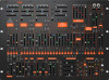
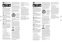
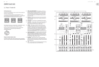
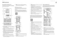
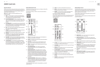
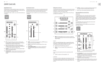
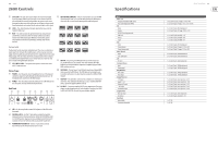
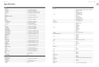
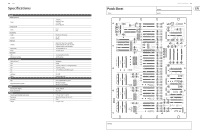
16 2600 2600 Controls (87) EXT CLK IN - This jack can be used to import an external clock signal to run the Sample & Hold circuit. Placing a 3.5 mm connector into this jack will disable the internal clock generator. Any square or pulse wave generated in other areas of the synthesizer, as well gate or trigger signals from the keyboard can be routed into this jack and used as a clock signal. (88) LEVEL - This slider attenuates the input signal before it goes into the Sample & Hold circuit. (89) RATE - This slider controls the speed of the internal clock generator and therefore controls how often the Sample & Hold circuit takes a measurement of the input signal. When the internal clock signal is interrupted by use of the EXT CLK IN input, the RATE slider will not function. (96) MIDI CHANNEL SWITCHES - These 4 switches allow you to set the MIDI Channel number from 1 to 16 (see the table printed in this document or refer to the silk-screened switch matrix printed on the back panel). 1 2 3 4 5 6 7 8 Electronic Switch The Electronic Switch connections are bidirectional. This circuit can alternate a single input from C between the A and B outputs, or the circuit can route two signals into the A and B jacks and then alternate the C output between the A and B input signals. The rate of back-and-forth switching in both of these scenarios is controlled by the Sample & Hold circuit's internal clock (or an external clock source routed in through the EXT CLK IN jack. (90) ELEC SWITCH A/B/C - These jacks route signals in and out over cables with 3.5 mm connectors. Phones/Power (91) PHONES - Use this jack to connect headphones that use 1/8" plugs and control the output level with the knob immediately below the jack. The headphone jack is connected to the Mixer output. (92) POWER - Press this switch to turn the synthesizer on or off. Make sure all the connections are made before turning on the unit. Back Panel (93) (94) (95) (96) (97) (98) (99) (100) 9 10 11 12 13 14 15 16 (97) MIDI IN - This port receives MIDI data from an external source over a 5-pin DIN connector. This external source will commonly be a MIDI keyboard, an external hardware sequencer, a computer equipped with a MIDI interface, and so on. (98) MIDI THRU - This port uses a 5-pin DIN jack is used to pass through MIDI data received at the MIDI IN jack. This MIDI data will commonly be sent to another synthesizer or to a drum machine assigned to a different MIDI Channel. (99) USB PORT - This jack allows connection to a computer over a USB type B connection. This synthesizer will show up as a class-compliant USB MIDI device, capable of supporting MIDI in and out. (100) DC INPUT - Connect the supplied 12V DC power adapter here. The power adapter can be plugged into an AC outlet capable of supplying from 100V to 240V at 50 Hz/60 Hz. Use only the power adapter supplied. (93) LED - Use this rotary knob to control the brightness of the LEDs on the front panel. (94) INTERVAL LATCH - Use this ¼" jack with an external footswitch to temporarily turn on the interval function. When the VOICE MODE switch is in the DUO position, playing two notes and depressing the footswitch maintains the two-note interval while you play further single notes. (95) PORTAMENTO FOOTSWITCH - Use this ¼" jack with an external footswitch to turn the Portamento function on or off. Specifications Inputs VCO 1 / 2 / 3 Frequency modulation (FM) control Pulse width modulation (PWM) VCF Audio Control ADSR / AR envelope generator S&H clock Gate in Trig in VCA Audio Control (linear) Control (exponential) Mixer / Reverb Audio Left / right inputs LFO Ext vib in Envelope Follower Input Preamp input Ring Modulator VCO 1 input VCO 2 input Voltage Processor -10 V input Inputs 1 / 3 / 5 Keyboard CV input +10 V input Env follower input Sample & Hold Noise gen input Ext clock in Back Panel Interval latch Portamento footswitch Quick Start Guide 17 11 x 3.5 mm TS jacks, CV range: -10 V to +10 V 2 x 3.5 mm TS jack, CV range: -5 V to +5 V, 1 V/10% 5 x 3.5 mm TS jacks, 50 kΩ unbalanced 3 x 3.5 mm TS jacks, CV range: -10 V to +10 V 1 x 3.5 mm TS jack, threshold: > 6 V 1 x 3.5 mm TS jack, threshold: +4 V 1 x 3.5 mm TS jack, threshold: +5 V 2 x 3.5 mm TS jacks, 50 kΩ unbalanced 1 x 3.5 mm TS jack, CV range: -10 V to +10 V 1 x 3.5 mm TS jack, CV range: -10 V to +10 V 2 x 3.5 mm TS jacks, 50 kΩ unbalanced 2 x 3.5 mm TS jacks, 50 kΩ unbalanced 1 x 3.5 mm TS jack, 50 kΩ unbalanced 1 x 3.5 mm TS jack, 100 kΩ unbalanced 1 x 3.5 mm TS jack, 100 kΩ unbalanced 1 x 3.5 mm TS jack, 100 kΩ unbalanced 1 x 3.5 mm TS jack, 100 kΩ unbalanced 1 x 3.5 mm TS jack, max. input level: +10 V 3 x 3.5 mm TS jacks, max. input level: +10 V 1 x 3.5 mm TS jack, max. input level: +10 V 1 x 3.5 mm TS jack, max. input level: +10 V 1 x 3.5 mm TS jack, max. input level: +10 V 1 x 3.5 mm TS jack, 50 kΩ unbalanced 1 x 3.5 mm TS jack, threshold: > 3 V 1 x 1/4" TRS 1 x 1/4" TRS
-
 1
1 -
2
-
3
-
 4
4 -
 5
5 -
 6
6 -
 7
7 -
 8
8 -
 9
9 -
 10
10 -
 11
11 -
 12
12 -
 13
13
 |
 |