Behringer AMP800 Manual - Page 5
Control Elements - miniamp
 |
View all Behringer AMP800 manuals
Add to My Manuals
Save this manual to your list of manuals |
Page 5 highlights
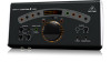
5 MINIAMP AMP800 User Manual 2. Control Elements The AMP800 is a headphone amplifier that includes 4 Headphone Channels, so you can share the AMP800 with other musicians. In addition, each musician can choose between 2 audio channels: Input Channel A and Input Channel B. ◊ Ensure that only qualified personnel set up and operate the AMP800. 2.1 Front panel This section describes how to use the front panel of the AMP800, illustrated as follows: (1) (2) (3) (4) (5) (6) (7) (8) Fig. 2.1: AMP800 front panel In the previous illustration, each control element is associated with a callout, for example (1). In this section, use these callouts to identify details about each control element. For each Input Channel (A and B), the front panel includes control elements (1) and (2). To manage the signal in each of these Input Channels, use these control elements: (1) LEVEL control: To adjust the input level of a signal, turn this control toward 0 (minimum level) or, alternatively 6 (maximum level). (2) BALANCE control: To adjust the stereo image of a signal, turn this control toward L (left) or, alternatively R (right). (3) A + B meter: To monitor the combined level of both signals (A and B), use this meter. An LED glows next to the value that identifies the combined level (-24 dB to 0 dB). If the signal is too strong, the CLIP LED glows. Most of the time, the optimal level is 0 dB (a full signal). For each Headphone Channel (1, 2, 3, and 4), the front panel includes control elements (4) through (7). To manage each Headphone Channel, use these control elements: (4) (headphone) connector: To connect a headphone, use this stereo, ¼" TRS connector. For details about TRS plugs, see 4. Audio Connections. (5) INPUT button: To select an Input Channel, push this button. When you listen to: • Input Channel A, this button is not pushed in and not lit • Input Channel B, this button is pushed in and lit (6) PHONES LEVEL control: To adjust the level of a headphone signal, turn this control toward 0 (minimum volume) or, alternatively 6 (maximum volume). (7) CH meter: To monitor the level of a headphone signal, use this meter. An LED glows next to the value that identifies the headphone volume (-24 dB to 0 dB). If the signal is too strong, the CLIP LED glows. Most of the time, the optimal volume is 0 dB (a full signal). (8) (power) button: To turn the AMP800 on and off, push this button. When you turn the AMP800: • on, this button is pushed in and lit • off, this button is not pushed in and not lit ◊ When you finish using the AMP800, unplug the power supply unit from the power source. As long as the power supply unit is connected to a power source, the power supply unit consumes energy.
-
 1
1 -
 2
2 -
 3
3 -
 4
4 -
 5
5 -
 6
6 -
 7
7 -
 8
8 -
 9
9 -
 10
10
 |
 |
