Behringer AMP800 Manual - Page 6
Setup Example - miniamp manual
 |
View all Behringer AMP800 manuals
Add to My Manuals
Save this manual to your list of manuals |
Page 6 highlights
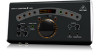
6 MINIAMP AMP800 User Manual 2.2 Rear panel This section describes how to use the rear panel to set up the AMP800. The following illustrates the rear panel of the AMP800: (9) (10) (11) (12) (13) Fig. 2.2: AMP800 rear panel In the previous illustration, each control element is associated with a callout, for example (1). In this section, use these callouts to identify details about each control element: (9) POWER connector: To power the AMP800, connect the power supply unit to this connector. This power supply unit is delivered with the AMP800. (10) PHONES OUT connectors: For each Headphone Channel (1, 2, 3, and 4), the rear panel includes an additional headphone connector, which is a stereo, ¼" TRS connector. (11) LINK OUT A connectors: If you need more than the 4 Headphone Channels that a single AMP800 provides, connect these balanced, ¼" TRS connectors (Left and Right) to the inputs of another AMP800. The LINK OUT A connectors send only the signal of Input Channel A, without any LEVEL or BALANCE settings. (12) INPUT connectors: For each Input Channel (A and B), the rear panel includes 2 balanced, ¼" TRS connectors (Left and Right). Connect them to the outputs of a mixer, a CD player, or a soundcard. For mono signals, use only the L connector. ◊ If the output is balanced and you insert unbalanced, ¼" TS plugs in the INPUT connectors, the signal level will decrease 6 dB. To raise the signal level, use the relevant LEVEL control ((1)). (13) SERIAL NUMBER: To register the AMP800, use this unique serial number. For details about TS and TRS plugs, see 4. Audio Connections. 3. Setup Example The following example illustrates the role of the AMP800 in your audio setups: L & R Input Phones Out < 1 PRO MIXER VMX100USB MINIAMP AMP800 MINIAMP AMP800 Fig. 3.1: Setup examplen L & R Input L & R Link Out A CD Player
-
 1
1 -
 2
2 -
 3
3 -
 4
4 -
 5
5 -
 6
6 -
 7
7 -
 8
8 -
 9
9 -
 10
10
 |
 |
