Behringer DSP110 Manual - Page 10
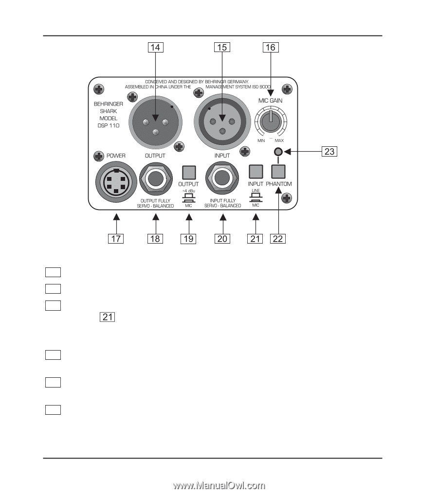
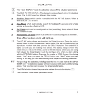
Fig 1.3: Rear panel control elements and connectors of the DSP110, MIC GAIN, POWER SUPPLY CONNECTOR - shark power supply
 |
View all Behringer DSP110 manuals
Add to My Manuals
Save this manual to your list of manuals |
Page 10 highlights
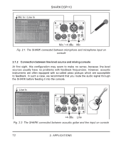
SHARK DSP110 Fig 1.3: Rear panel control elements and connectors of the DSP110 14 This is the SHARK’s balanced XLR output. 15 This is the SHARK’s balanced XLR input. 16 The MIC GAIN control adjust the input signal gain, when the INPUT LEVEL switch has been pressed (position: MIC). To adjust microphone levels you can use the CLIP LEVEL indicator, by setting the CLIP LEVEL control to midtravel position. Please make sure that the CLIP LED will not light up. 17 Use the POWER SUPPLY CONNECTOR to hook up the SHARK’s external power supply. 18 This is the SHARK’s balanced JACK output, which carries the same signal as the XLR output. 19 The OUTPUT LEVEL switch controls the reference level provided by the outputs of the DSP110. Possible values are: +4 dBu or microphone level. 10 1. INTRODUCTION
-
 1
1 -
2
-
3
-
4
-
 5
5 -
 6
6 -
 7
7 -
 8
8 -
 9
9 -
 10
10 -
 11
11 -
 12
12 -
 13
13 -
 14
14 -
 15
15 -
16
-
17
-
18
-
19
-
20
-
21
-
22
-
23
-
24
-
25
-
26
 |
 |