Behringer DSP110 Manual - Page 11
Applications
 |
View all Behringer DSP110 manuals
Add to My Manuals
Save this manual to your list of manuals |
Page 11 highlights
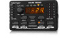
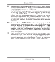
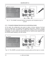
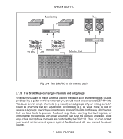
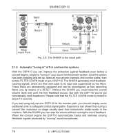
SHARK DSP110 20 This is the SHARK’s balanced JACK input, which is wired in parallel to the XLR input. 21 Use the INPUT LEVEL switch to select the input sensitivity (microphone or line levels). In LINE mode, you can use the CLIP LEVEL control to adapt the internal level settings to the digital circuitry. Please make sure that the CLIP-LED will not light up. 22 The PHANTOM switch enables the Phantom Power supply required for condenser microphones. 23 The PHANTOM CONTROL LED lights up when Phantom Power is on. 2. APPLICATIONS 2.1 Wiring the DSP110: general remarks With its great versatility the SHARK can be used for a variety of applications. This chapter describes connection and configuration examples of the most common applications. 2.1.1 Connection between microphone and mixing console In live applications it is often useful to protect specific single microphones against feedback. We therefore recommend that you connect the SHARK between your microphone and a microphone input on your mixing console (OUTPUT LEVEL switch set to MIC). If all mic inputs are in use, you can set the SHARK’s OUTPUT switch to +4 dBu (switch pressed) and adapt the output signal of your SHARK to a line input on your console using the MIC GAIN control. To prevent the occurrence of subsonics you can activate the SHARK’s Low Cut filter. Switch on Phantom Power when you are using condenser microphones. 2. APPLICATIONS 11
-
 1
1 -
2
-
3
-
4
-
5
-
 6
6 -
 7
7 -
 8
8 -
 9
9 -
 10
10 -
 11
11 -
 12
12 -
 13
13 -
 14
14 -
 15
15 -
 16
16 -
17
-
18
-
19
-
20
-
21
-
22
-
23
-
24
-
25
-
26
 |
 |
