Behringer EURODESK SX2442FX Manual - Page 7
Stereo channels - case for
 |
View all Behringer EURODESK SX2442FX manuals
Add to My Manuals
Save this manual to your list of manuals |
Page 7 highlights
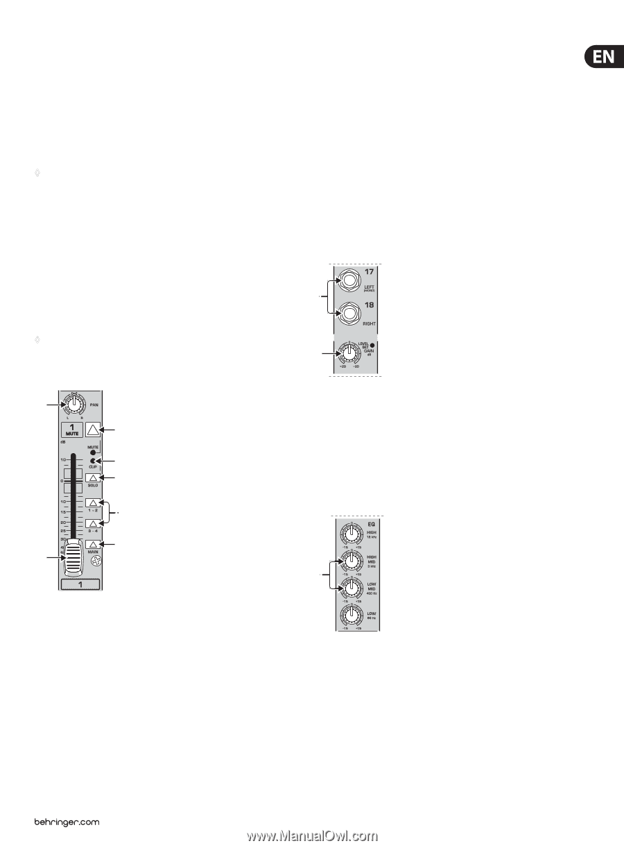
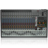
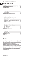
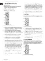
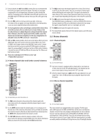
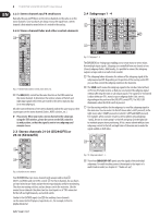
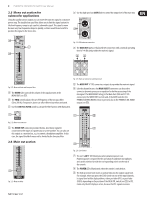
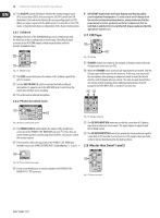
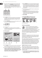
7 EURODESK SX3242FX/SX2442FX User Manual (9) On each channel, the AUX 1 and AUX 2 controls allow you to determine the level of the aux signals sent from the channel. The main aux send signal comprising the aux send signals from all channels can then be adjusted with the corresponding master AUX SEND controls (51), and is present at the AUX SEND outputs (52). Both aux sends are mono, post-EQ, with a gain of up to +15 dB. (10) Press the PRE switch to set all aux sends to pre-fader. In this case, the volume of the aux signals is no longer dependent on the fader position, so you can create completely independent monitor mixes. ◊ For most applications when controlling an external effects device from one of the aux buses, the aux sends must be set post-fader, so that the effect volume in a channel depends on the position of the channel fader. Otherwise, the effect signal would still be audible, even if the channel was turned down completely. For this type of application it is advisable to leave the PRE switch out (= not pressed). (11) FX 1 and FX 2 controls provide a direct route to the built-in effects processor. Additionally, they can be used to control an external effects unit, via the FX SEND 1 and 2 outputs (similar to the AUX SEND 1 and 2 jacks). To ensure that the internal effects processor and the FX SEND outputs actually get a signal, the corresponding FX control must not be set fully counter-clockwise (-oo), and the master FX SEND (see (60)) must be turned up. The FX buses are hard wired post-fader. ◊ Please also read chapter 2.10 "Effects section" and 3 "Digital effects processor". (15) The SOLO switch routes the channel signal to the solo bus (Solo In Place) or the PFL bus (Pre Fader Listen). Thus, you can monitor a channel signal without affecting the main output signal. The signal to be monitored is taken either pre (PFL, mono) or post-panorama control (Solo, stereo) and post-channel fader (depending on the position of the SOLO/PFL switch (40)). (16) The SUB switch routes the signal to the respective subgroups. Your EURODESK features 4 subgroups (1-2 and 3-4). With the PAN control on the input channel (see (12)) you can determine to which of the two groups the signal is routed (hard left: sub 1 or 3, hard right: sub 2 or 4). (17) The MAIN switch routes the signal to the main mix. (18) The channel fader governs the level of the channel signal as part of the main mix (or submix). 2.2 Stereo channels 2.2.1 Channel inputs (19) (20) 2.1.4 Mono channel fader and further control elements (12) (13) (14) (15) Fig. 2.5: Stereo channel inputs (19) Each stereo channel is equipped with two balanced line-level inputs on ¼" TRS connectors for the left and right channels. The channels can also process mono signal, as long as you use the "LEFT" jack only. (20) All stereo channel strips have a GAIN control for gain adjustment. Its scale ranges from +20 to -20 dB and allows you to adapt the input level to the line inputs. 2.2.2 Stereo channel equalizer (16) (17) (18) (21) Fig. 2.4: Channel fader, pan control, mute button, etc. (12) The PAN control determines the position of the channel signal in the stereo mix as well as the subgroup to which the channel signal is routed (see chapter 2.4). (13) Use the MUTE switch to mute the channel signal, so it is no longer part of the main mix. At the same time, all aux buses set to post-fader are muted for the respective channel, while the pre-fader monitor buses remain operative. The MUTE LED is illuminated when the channel is muted. (14) The CLIP LED illuminates when the channel overloads. In this case, please reduce the input gain using the GAIN control. This LED also illuminates when you activate the solo function with the SOLO switch below. Fig. 2.6: Stereo channel equalizer The stereo channels are equipped with a stereo equalizer. The filter types and cutoff frequencies for HIGH and LOW filters are the same as on the mono channels. Instead of one semi-paramtric midrange band, the stereo channels have two separate midrange bands (21) (HIGH MID and LOW MID) with fixed mid-frequencies (3 kHz and 400 Hz). Stereo EQs are preferable for processing the frequency response of stereo signals. With two mono equalizers you might encounter problems with different settings between the left and right channels.
-
 1
1 -
 2
2 -
 3
3 -
 4
4 -
 5
5 -
 6
6 -
 7
7 -
 8
8 -
 9
9 -
 10
10 -
 11
11 -
 12
12 -
13
-
14
-
15
-
16
-
17
-
18
-
19
-
20
 |
 |