Behringer EUROLIGHT LC2412 Manual - Page 7
°2°, Control elements of the A PRESET Control elements of the B MEMORY, - user manual
 |
View all Behringer EUROLIGHT LC2412 manuals
Add to My Manuals
Save this manual to your list of manuals |
Page 7 highlights
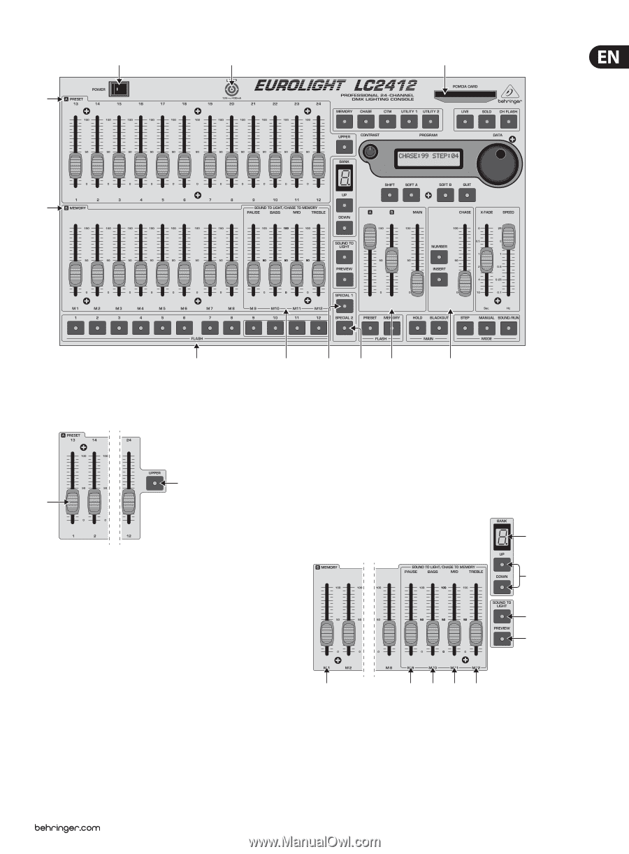
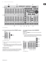
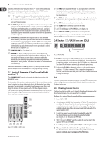
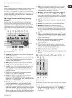
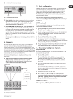
7 EUROLIGHT LC2412 User Manual (10) (11) (5) (1) (2) Fig. 2.1: Section overview (4) (3) (8) (9) (6) (7) 2.1 Control elements of the A PRESET section (33) (12) 2.2 Control elements of the B MEMORY section ( 2 ) The faders of the B MEMORY section are located in the block underneath the A PRESET section. (13) These faders control the illumination level of an entire group of channels in a ratio to one another that you previously determined by setting up the A PRESET faders and saving this setting as a memory. (18) Fig. 2.2: A PRESET section (detail) (12) Faders 1-12. Used to set the intensity of light elements connected to the (19) dimmer pack. (33) UPPER switch. When you press this switch, the A PRESET section is switched to the twelve additional channels. After that, you can set up the intensity of (20) channels 13 - 24. See also chapter 3.2. (21) Setting up presets Channel faders are used for setting up a preset that can be directly recalled by moving fader A (41). As in all other setups, the MAIN fader (43) (see chapter 2.6) determines the maximum illumination level of selected light sources. (13) Fig. 2.3: B MEMORY section (14) (15) (16) (17)
-
 1
1 -
 2
2 -
 3
3 -
 4
4 -
 5
5 -
 6
6 -
 7
7 -
 8
8 -
 9
9 -
 10
10 -
 11
11 -
 12
12 -
13
-
14
-
15
-
16
-
17
-
18
-
19
-
20
-
21
-
22
-
23
-
24
-
25
-
26
 |
 |