Behringer MULTIGATE PRO XR4400 Manual - Page 7
The Design Concept, Installation - multigate pro model
 |
View all Behringer MULTIGATE PRO XR4400 manuals
Add to My Manuals
Save this manual to your list of manuals |
Page 7 highlights
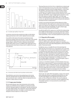
7 MULTIGATE PRO XR4400 User Manual 2. The Design Concept 2.1 High quality components and design The philosophy behind BEHRINGER products guarantees a no-compromise circuit design and employs the best choice of components. The operational amplifiers NJM4580 which are used in the MULTIGATE PRO, are exceptional. They boast extreme linearity and very low distortion characteristics. To complement this design the choice of components includes high tolerance resistors and capacitors, detent potentiometers and several other stringently selected elements. For the first time, the MULTIGATE PRO XR4400 uses SMD technology (Surface Mounted Device). These sub-miniature components known from aerospace technology allow for an extreme packing density, plus the unit's reliability could be improved. Additionally, the unit is manufactured in compliance with a ISO9000 certified management system. ◊ If the unit is damaged, please do not return it to us, but notify your dealer and the shipping company immediately, otherwise claims for damage or replacement may not be granted. Shipping claims must be made by the consignee. Please take the time to complete and return the warranty card within 14 days of the date of purchase, otherwise you will lose the right to the extended warranty. Or just use our online-registration (behringer.com). 3.1 Rack mounting The BEHRINGER MULTIGATE PRO fits into one standard 19" rack unit of space (1 ¾"). Please allow at least an additional 4" depth for the connectors on the back panel. Be sure that there is enough air space around the unit for cooling and please do not place the MULTIGATE PRO on high temperature devices such as power amplifiers etc. to avoid overheating. 2.2 Inputs and outputs 2.2.1 Balanced inputs and outputs As standard, the BEHRINGER MULTIGATE PRO is installed with electronically servo-balanced inputs and outputs. The new circuit design features automatic hum and noise reduction for balanced signals and thus allows for trouble-free operation, even at high operating levels. Externally induced mains hum etc. will be effectively suppressed. The automatic servo-function recognizes the presence of unbalanced connectors and adjusts the nominal level internally to avoid level differences between the input and output signals (correction 6 dB). 3. Installation Your BEHRINGER MULTIGATE PRO was carefully packed in the factory and the packaging was designed to protect the unit from rough handling. Nevertheless, we recommend that you carefully examine the packaging and its contents for any signs of physical damage, which may have occurred in transit. 3.2 Mains voltage Before you connect your MULTIGATE PRO to the mains, please make sure that your local voltage matches the voltage required by the unit! The fuse holder on the female mains connector has 3 triangular markers, with two of these triangles opposing each other. Your MULTIGATE RPO is set to the operating voltage printed next to these markers, and can be set to another voltage by turning the fuse holder by 180°. CAUTION: this instruction does not apply to export models exclusively designed, e.g. for 115 V operation! 3.3 Audio connections The audio inputs and outputs on the BEHRINGER MULTIGATE PRO are fully balanced. If possible, connect the unit to other devices in a balanced configuration to allow for maximum interference immunity. ◊ Please ensure that only qualified persons install and operate the MULTIGATE PRO. During installation and operation the user must have sufficient electrical contact to earth. Electrostatic charges might affect the operation of the MULTIGATE PRO! Output Pin 1 Pin 2 = (+) Signal Pin 3 = (-) Signal 2 1 3 Cable Shield (+) Signal + Hum (-) Signal + Hum 1 2 3 Input Ground Positive Negative RFI and Hum Fig. 3.1: Compensation of interference with balanced connections (+)Hum + Signal (-)Hum + Signal 2 x Signal = Signal + 6 dB
-
 1
1 -
 2
2 -
 3
3 -
 4
4 -
 5
5 -
 6
6 -
 7
7 -
 8
8 -
 9
9 -
 10
10 -
 11
11 -
 12
12 -
13
-
14
-
15
 |
 |
