Behringer MULTIGATE PRO XR4400 Manual - Page 9
Technical Background - multigate pro noise gate
 |
View all Behringer MULTIGATE PRO XR4400 manuals
Add to My Manuals
Save this manual to your list of manuals |
Page 9 highlights
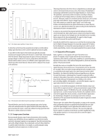
9 MULTIGATE PRO XR4400 User Manual ◊ The HOLD control is enabled in GATE mode only! (8) The RELEASE control determines the time of the release process. This process begins after the end of the hold phase and ends when the gain reduction adjusted with the RANGE control is achieved. The setting range of the RELEASE control is from 0.05 to 4 seconds. ◊ The RELEASE control is enabled in GATE mode only! (9) The MODE switch is used to set the operating mode of the respective channel. When the switch is out, the corresponding section works as an ultra-fast gate. In this mode, even percussive signals can be processed without any signal loss. With the MODE function on, the IRC expander (Interactive Ratio Control) is activated. This interactive control function allows for the program-dependent expansion of complex signals. Both the attack time and the fade-out characteristics (ratio) vary depending on the program material. The agreeable results of this automatic process are less critical adjustment work and "inaudible" expansion of the program material. (10) The RANGE/RATIO control performs a dual function: depending on the position of the MODE switch (i.e. depending on the operating mode of the unit: gate or expander), the RANGE/RATIO control determines the maximum amount of gain reduction or the expansion curve. In gate mode, this control adjusts the RANGE determining the amount of maximum gain reduction from 0 dB to -80 dB. In expander mode, it works as a RATIO control setting the expansion ratio. The ratio function determines the input vs. output level ratio, for all signals below the threshold. The setting range is from 1:1 to 1:4. (11) The 8-digit GAIN REDUCTION meter informs you about the current amount of gain reduction within a range from 1 to 40 dB. (12) When you press the COUPLE switch, this channel is automatically configured as a "slave" channel. Its left neighbor becomes the "master" now controlling both channels in all their parameters. 4.2 The rear panel elements (13) BEHRINGER MULTIGATE PRO MODEL XR4400 CONCEIVED AND DESIGNED BY BEHRINGER GERMANY. MADE IN CHINA. ALL INPUTS & OUTPUTS FULLY BAL ANCED TIP/PIN 2 RING/PIN 3 SLEEVE/PIN 1 OUTPUTS 4 INPUTS 4 (14) (16) (15) Fig. 4.3: Rear panel elements ALL INPUTS & OUTPUTS FULLY BALANCED TIP/PIN 2 RING/PIN 3 SLEEVE/PIN 1 0UTPUTS 3 INPUTS 3 ALL INPUTS & OUTPUTS FULLY BALANCED TIP/PIN 2 RING/PIN 3 SLEEVE/PIN 1 0UTPUTS 2 INPUTS 2 ALL INPUTS & OUTPUTS FULLY BALANCED TIP/PIN 2 RING/PIN 3 SLEEVE/PIN 1 0UTPUTS 1 INPUTS 1 (13) FUSE HOLDER / VOLTAGE SELECTOR. Please make sure that your local voltage matches the voltage indicated on the unit, before you attempt to connect and operate the MULTIGATE PRO. Blown fuses may only be replaced by fuses of the same type and rating. (14) MAINS CONNECTION. Use the enclosed power cord to connect the unit to the mains. Please also note the instructions given in the "Installation" chapter. (15) AUDIO IN. These are the audio inputs of your MULTIGATE PRO, available both as balanced 6.3 mm jack and XLR connectors. (16) AUDIO OUT. These are the audio outputs of your MULTIGATE PRO. Matching phone jack and XLR connectors are wired in parallel. 5. Technical Background 5.1 EXPANDER mode As already described, a so-called downward expander automatically reduces the overall level of all signals that drop below an adjustable threshold, and thus expands the dynamic range of the program material. In other words, an expander is the opposite of a compressor. Expanders usually work with a relatively flat ratio curve to fade out the signal smoothly. Noise gates are a special form of expander using a much steeper ratio curve to abruptly cut the signal when it drops below the threshold. As expanders and gates are quite similar in what they do the following description of expanders and their functionalities also applies to noise gates. amplitude max. input audio signal min. masked noise 0 amplitude max. audible noise output audio signal min. masked noise 0 audible noise Fig. 6.1: Expander mode time threshold time 5.2 Interactive control functions Like the COMPOSER, INTELLIGATE, MULTICOM, and others, the MULTIGATE PRO uses the newly developed INTERACTIVE principle based on a chain of intelligent control functions. For example, the IRC expander (Interactive Ratio Control) does not use a fixed ratio curve but varies this curve depending on the input level and the setting of the THRESHOLD control.
-
 1
1 -
2
-
3
-
 4
4 -
 5
5 -
 6
6 -
 7
7 -
 8
8 -
 9
9 -
 10
10 -
 11
11 -
 12
12 -
 13
13 -
 14
14 -
15
 |
 |
