Behringer NX6000D Quick Start Guide - Page 6
NX6000/NX3000/NX1000/NX4-6000 Controls - amplifier
 |
View all Behringer NX6000D manuals
Add to My Manuals
Save this manual to your list of manuals |
Page 6 highlights
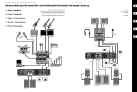
10 NX6000/NX3000/NX1000/NX4-6000/NX6000D/NX3000D/NX1000D NX6000/NX3000/NX1000/NX4-6000 Controls (1) (2) (3) (4) (6) (2) (5) (13) (7) NX3000/NX1000 (14) (8) (9) (10) (11) (12) (10) (13) (7) NX6000 (1) (2) (8) (9) (11) (12) (3) (4) (6) (2) (5) (14) (10) (13) (7) NX4-6000 (8) (9) (11) (12) 11 Quick Start Guide (EN) Step 2: Controls (1) RACK EARS secure the unit into a rack using four attaching screws and washers (fasteners not included). Requires two rack units. (2) VENTILATION openings allow back-to-front air circulation to prevent overheating. (3) SIGNAL, LIMIT and PROTECT LEDs display the signal level and system status for each channel. The SIGNAL LEDs light to show the input signal level. The LIMIT LED lights when the input signal exceeds an optimum level and activates the internal limiter. Reduce the input gain if the red LIMIT LED lights up continuously. The PROTECT LED shows when an operation error has occurred (over current, over temperature, and so on). When an operation error occurs, the PROTECT LED will light and the unit will automatically mute the channel until the error is no longer detected, after which the PROTECT LED will switch off and the amp will behave normally. (4) POWER LED lights up to indicate the unit is powered on. (5) INPUT CONTROLS adjust the input level. To increase signal gain, rotate the knobs clockwise; to reduce the gain, rotate the knobs counter-clockwise. (6) POWER button turns the amplifier on and off. (7) POWER SOURCE jack accepts the included IEC power cable. (8) OUTPUTS connect the amplifier to the speakers using professional speaker cables with twist-locking plugs. (9) PIN OUT MATRIX lists the output pin/channel configurations available in each speaker output jack. (10) VENTILATION FAN speed adjusts automatically to ensure troublefree operation. (11) MODE SWITCH Choose the amplifier mode by toggling the sliding MODE SWITCH between the MONO, STEREO, and BRIDGE positions (NX6000: no BRIDGE mode.) 2 2 2 (12) CROSSOVER switch chooses between three modes: FULLRANGE, LF (low frequency crossover) and HF (high frequency crossover). In LF mode, the unit amplifies only the low frequencies of the signal. In HF mode, the unit only amplifies the high frequencies. LF and HF modes are typically used in bi-amping applications. (13) INPUTS Route line-level input signals into these combination jacks using XLR, balanced ¼" TRS, or unbalanced ¼" TS connectors. XLR Plug ¼" TS Plug ¼" TRS Plug (14) BREAKER (automated fuse, NX6000 and NX4-6000 only). After eliminating the cause of faulty operation, simply depress the BREAKER and power up the unit again. The BREAKER acts in place of common discardable fuses. BREAKER WARNING: Take the following actions BEFORE resetting the breaker: • Unplug the AC main cable • Press the POWER button to the extended "OFF" position • Turn all input gain control elements down • And then, reset the breaker, connect the unit to the mains, switch ON and slowly increase the gain to the target volume
-
 1
1 -
 2
2 -
 3
3 -
 4
4 -
 5
5 -
 6
6 -
 7
7 -
 8
8 -
 9
9 -
 10
10 -
 11
11 -
 12
12 -
13
-
14
-
15
-
16
-
17
-
18
-
19
-
20
-
21
-
22
-
23
 |
 |
