Behringer NX6000D Quick Start Guide - Page 9
NX6000D/NX3000D/NX1000D Controls - setup
 |
View all Behringer NX6000D manuals
Add to My Manuals
Save this manual to your list of manuals |
Page 9 highlights
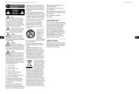
16 NX6000/NX3000/NX1000/NX4-6000/NX6000D/NX3000D/NX1000D NX6000D/NX3000D/NX1000D Controls (1) (2) (4) (6) (8) (9) (2) (3) (5) (7) (10) (11) (17) (12) (13) (14) (15) (16) NX3000D/NX1000D (1) (2) (4) (6) (8) (9) (2) (3) (5) (7) (10) (11) (18) (15) (17) (12) NX6000D (13) (14) (16) 17 Quick Start Guide (EN) Step 2: Controls (1) RACK EARS secure the unit into a rack using four attaching screws and washers (fasteners not included). Requires two rack units. (2) VENTILATION openings allow back-to-front air circulation to prevent overheating. (3) INPUT CONTROLS adjust the input level. To increase signal gain, rotate the knobs clockwise; to reduce the gain, rotate the knobs counter-clockwise. (4) SIGNAL, LIMIT and PROTECT LEDs display the signal level and system status for each channel. The SIGNAL LEDs light to show the input signal level. The LIMIT LED lights when the input signal exceeds an optimum level and activates the internal limiter. Reduce the input gain if the red LIMIT LED lights up continuously. The PROTECT LED shows when an operation error has occurred (over current, over temperature, and so on). When an operation error occurs, the PROTECT LED will light and the unit will automatically mute the channel until the error is no longer detected, after which the PROTECT LED will switch off and the amp will behave normally. (5) SETUP button steps through parameters within DSP processing modules. (6) LCD SCREEN displays the current DSP module and parameter settings. (7) PROCESS button steps through the DSP processing modules. (8) UP/DOWN buttons step through DSP modules. (9) EXIT button takes you back to the top-level DSP screen. (10) SELECT encoder knob toggles between Graphic and Edit modes (when pressed) and changes parameter values (when rotated). (11) POWER button turns the amplifier on and off. (12) POWER SOURCE jack accepts the included IEC power cable. (13) OUTPUTS connect the amplifier to the speakers using professional speaker cables with twist-locking plugs. (14) PIN OUT MATRIX lists the output pin/channel configurations available in each speaker output jack. (15) VENTILATION FAN speed adjusts automatically to ensure troublefree operation. (16) INPUTS Route line-level input signals into these combination jacks using XLR, balanced ¼" TRS, or unbalanced ¼" TS connectors. XLR Plug ¼" TS Plug ¼" TRS Plug (17) USB connection enables firmware updates and control over parameters via computer. Please visit behringer.com to download DSP control software for your computer. The USB port is for amplifier configuration only. (18) BREAKER (automated fuse, NX6000D). After eliminating the cause of faulty operation, simply depress the BREAKER and power up the unit again. The BREAKER acts in place of common discardable fuses. BREAKER WARNING: Take the following actions BEFORE resetting the breaker: • Unplug the AC main cable • Press the POWER button to the extended "OFF" position • Turn all input gain control elements down • And then, reset the breaker, connect the unit to the mains, switch ON and slowly increase the gain to the target volume
-
 1
1 -
2
-
3
-
 4
4 -
 5
5 -
 6
6 -
 7
7 -
 8
8 -
 9
9 -
 10
10 -
 11
11 -
 12
12 -
 13
13 -
 14
14 -
15
-
16
-
17
-
18
-
19
-
20
-
21
-
22
-
23
 |
 |
