Behringer UB2442FX-PRO User Manual - Page 10
XPQ Surround function UB1832FX-PRO only, 3.8 CD/Tape input, CD/tape output, 3.9 Lamp socket
 |
View all Behringer UB2442FX-PRO manuals
Add to My Manuals
Save this manual to your list of manuals |
Page 10 highlights
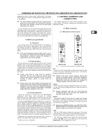
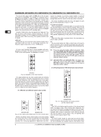
EURORACK UB1622FX-PRO/UB1832FX-PRO/UB2222FX-PRO/UB2442FX-PRO 2.3.8 CD/Tape input, CD/tape output Fig. 2.13: The FX/AUX 2 return fader of the UB1832FX-PRO MON The MON switch routes the signals appearing at the AUX RETURN 2 jacks to the monitor path, along with the monitor signals from the channels. If you wish to route the effect signal to the monitor mix, you can also switch aux 1 to pre-fader, drive the effect device from the aux 1 output and return the effect signal via AUX RETURN 2 to the monitor signal. 2.3.7 XPQ Surround function (UB1832FX-PRO only) Fig. 2.15: 2-track connectors and lamp socket CD/TAPE INPUT The CD/TAPE INPUT jacks (RCA) are designed to accept a 2-track recorder (e.g. DAT recorder), or they can be used as stereo line input. The output signal of a second EURORACK or the BEHRINGER ULTRALINK PRO MX882 can also be connected here. If you connect the output of a hi-fi amplifier (with a source selection switch) to the CD/TAPE INPUT, you can easily listen to additional sources (e.g. cassette recorder, MD player, sound card, etc.). Using the voice canceller function (UB1832FX-PRO only), you can process all signals being brought into your mixing console via these connectors. CD/TAPE OUTPUT These connectors are wired in parallel to the MAIN OUT and carry the main mix signal (unbalanced). Connect this to the inputs of your recording device. The final output level can be adjusted via the high-precision MAIN MIX fader. + If you connect a compressor or a noise gate post CD/TAPE OUTPUT, the main mix fader will probably not be able to create a satisfactory fade-out effect. 2.3.9 Lamp socket (UB2442FX-PRO only) Use this BNC socket to connect a gooseneck lamp (12 V DC, max. 0.5 A). 2.3.10 Level meter and monitoring Fig. 2.14: Control elements of the surround function The XPQ surround function can be enabled/ disabled with the XPQ TO MAIN switch. This is a built-in effect that widens the stereo width, thus making the sound more lively and transparent. Use the SURROUND control to determine the intensity of this effect. VOICE CANCELLER Here, you have a filter circuitry that lets you almost entirely remove the vocal portion of a recording. The filter is constructed in such a way that voice frequencies are targeted without majorly affecting the rest of the signal. Additionally, the filter seizes only the middle of the stereo image, exactly there where the vocals are typically located. + Connect the signal sources you wish to process using the Voice Canceller to the CD/TAPE INPUT connectors. The Voice Canceller circuitry is not available for other inputs. Possible applications for the Voice Canceller are obvious: you can very simply stage background music for Karaoke events. Of course, you can also do this at home or at your rehearsal room before you hit the stage. Singers with their own band can practice singing difficult parts using a complete playback from a tape player or a CD, thus minimizing rehearsal time. Fig. 2.16: Control room and phones sections of the UB2442FX-PRO CD/TAPE The CD/TAPE switch routes the signal from the CD/TAPE INPUT jacks to the level meter, the CONTROL ROOM OUT outputs and the PHONES jack—this is a simple way to check recorded signals via monitor speakers or headphones. SUB 1-2 or SUB The SUB 1-2 switch routes subgroup 1-2 to the level meter, CONTROL ROOM OUT and phones. SUB 3-4 The SUB 3-4 switch performs a similar function for subgroup 3-4 (UB2442FX-PRO only). MAIN MIX The MAIN MIX switch sends the main mix to the CONTROL ROOM OUT and the PHONES output as well as to the level meter. 10 2. CONTROL ELEMENTS AND CONNECTORS
-
 1
1 -
2
-
3
-
4
-
 5
5 -
 6
6 -
 7
7 -
 8
8 -
 9
9 -
 10
10 -
 11
11 -
 12
12 -
 13
13 -
 14
14 -
 15
15 -
16
 |
 |
