Behringer UB2442FX-PRO User Manual - Page 6
Control Elements And Connectors - case
 |
View all Behringer UB2442FX-PRO manuals
Add to My Manuals
Save this manual to your list of manuals |
Page 6 highlights
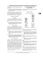
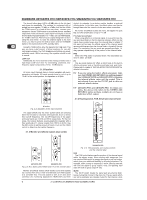
EURORACK UB1622FX-PRO/UB1832FX-PRO/UB2222FX-PRO/UB2442FX-PRO The second value range (+10 to -40 dB) refers to the line input and shows its sensitivity. The settings for equipment with st andard line-level signals (-10 dBV or +4 dBu) look like this: While the TRIM control is turned all the way down, connect your equipment. Set the TRIM control to the external devices’ standard output level. If that unit has an output signal level display, it should show 0 dB during signal peaks. For +4 dBu, turn up TRIM slightly, for -10 dBV a bit more. Fine-tuning of a signal being fed in is done using the level meter. To route the channel signal to the level meter, you have to press the SOLO switch and set the MODE switch in the main section to PFL (LEVEL SET). Using the TRIM control, drive the signal to the 0-dB mark. This way you have a vast amount of drive headroom for use with very dynamic signals. The CLIP display should light up only rarely, preferably never. While fine-tuning, the equalizer should be set to neutral. LOW CUT Additionally, the mono channels of the mixing consoles have a high-slope LOW CUT filter for eliminating unwanted, lowfrequency signal components (75 Hz, 18 dB/octave). 2.1.2 Equalizer All mono input channels have a 3-band equalizer with semiparametric mid bands. All bands provide boost or cut of up to 15 dB. In the central position, the equalizer is off (flat). routed, for example, to an active monitor speaker or external effects device. In the latter case, the effects return can then be brought back into the console via the aux return connectors. All monitor and effects busses are mono, are tapped into post EQ and offer amplification of up to +15 dB. Pre-fader/post-fader When using effects on a channel signal, it is usual to have the aux send post fader so that the balance between effect and dry signal stays constant even when the channel fader is altered. If this were not the case, the effects signal of the channel would remain audible even when the channel fader is turned all the way down. For monitoring, the aux sends are generally pre-fader, i.e. they operate independently of the position of the channel fader. PRE When the PRE switch is pressed down, the associated aux send is taken pre-fader. FX The aux send marked FX offers a direct route to the built-in effects processor and is therefore post-fader and post-mute. Please refer to chapter 4 “DIGITAL EFFECTS PROCESSOR” for detailed information. + If you are using the built-in effects processor, make sure that STEREO AUX RETURN 3 has nothing plugged into it (UB2442FX-PRO and UB2222FX-PRO), otherwise the internal effects return will be muted. This is not relevant if you use the FX OUT jack to drive an external effects device. + UB1622FX-PRO and UB1832FX-PRO: On these con- soles, the above note refers to the STEREO AUX RETURN 2 jacks as these models do not have a dedicated effect output. 2.1.4 Routing switch, PAN, SOLO and channel fader Fig. 2.2: Equalizer of the input channels The upper (HIGH) and the lower (LOW) bands are shelving filters that increase or decrease all frequencies above or below their cut-off frequency. The cut-off frequencies of the upper and lower bands are 12 kHz and 80 Hz respectively. For the mid range, the console features a semi-parametric equalizer with a filter quality (Q) of 1 octave, tunable from 100 Hz to 8 kHz. Use the MID control to set the amount of boost or cut, and the FREQ control to determine the central frequency. 2.1.3 Monitor and effects busses (Aux sends) Fig. 2.3: Aux Send control MON and FX in the channel strips Monitor and effects busses (AUX sends) source their signals via a control from one or more channels and sum these signals to a so-called bus. This bus signal is sent to an aux send connector (for monitoring applications: MON OUT) and then Fig. 2.4: The panorama and routing controls and the channel fader PAN The PAN control determines the position of the channel signal within the stereo image. When working with subgroups, you can use the PAN control to assign the signal to just one output, which gives you additional flexibility in recording situations. For example, when routing to subgroups 3 and 4, panning hard left will route the signal to group output 3 only, and panning hard right will route to group output 4 only. MUTE The MUTE switch breaks the signal path pre-channel fader, hence muting that channel in the main mix. The aux sends which are set to post-fader are likewise muted for that channel, while 6 2. CONTROL ELEMENTS AND CONNECTORS
-
 1
1 -
 2
2 -
 3
3 -
 4
4 -
 5
5 -
 6
6 -
 7
7 -
 8
8 -
 9
9 -
 10
10 -
 11
11 -
 12
12 -
13
-
14
-
15
-
16
 |
 |
