Behringer ULTRAGRAPH DIGITAL DEQ1024 Manual - Page 13
Specifications - equalizer ultragraph digital
 |
View all Behringer ULTRAGRAPH DIGITAL DEQ1024 manuals
Add to My Manuals
Save this manual to your list of manuals |
Page 13 highlights
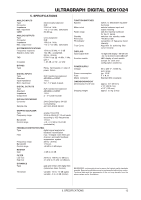
ULTRAGRAPH DIGITAL DEQ1024 5. SPECIFICATIONS ANALOG INPUTS Type Connector Impedance Max. input level CMRR ANALOG OUTPUTS Type Connector Impedance Max. output level SYSTEM SPECIFICATIONS Frequency response Signal-to-noise ratio THD Crosstalk BYPASS Type DIGITAL INPUTS Type Standard Input impedance Nom. input level DIGITAL OUTPUTS Type Standard Impedance Output level DIGITAL PROCESSING Converter Sample rate electronically balanced XLR 22 kΩ at 1 kHz +12 or +22 dBu, switchable 80 dB typ. servo-balanced XLR 100 Ω at 1 kHz +12 or +22 dBu, switchable 15 Hz to 35 kHz, +/- 3 dB 104 dBu, a-weighted, 22 Hz - 22 kHz 0.004 % typ. @ +4 dBu, 1 kHz, gain 1 < -85 dB, 22 Hz - 22 kHz Relay, hard-bypass in case of power failure XLR transformer-balanced AES/EBU or S/PDIF 110 Ω 0.2 - 5 V peak-to-peak XLR transformer-balanced AES/EBU or S/PDIF 110 Ω 2 - 5 V peak-to-peak 24-bit Delta-Sigma, 64/128 oversampling 44.1 kHz, 48 kHz, 96 kHz FUNCTION SWITCHES Bypass Meter in/out Fader range Standby Pink noise FB indicator True Curve DISPLAYS Input/output level Function switch POWER SUPPLY Voltage Power consumption Fuse Mains connector DIMENSIONS/WEIGHT Dimensions (H x W x D) Shipping weight switch, to deactivate equalizer functions selects between input and output metering sets the maximal cut/boost for the 31 bands switches into standby mode -48 dB to 0 dB recognition of frequency band intensity Algorithm for achieving filter curve linearity 12-digit LED display: -48/-36/-24/ -18/-12/-6/-3/0/+3/+6/+9 dB/CLIP LED display of each switch (except for clock and configuration switches) 85 to 250 V~, 50/60 Hz, auto range typ. 10 W T 1A H Standard IEC receptacle approx. 3.5" (89 mm) x 19" (482.6 mm) x 5.3" (135 mm) approx. 2.5 kg (5 lbs) GRAPHIC EQUALIZER Type Frequency range Bandwidth Control range analog 1/3-oct EQ 20 Hz to 20 kHz 31 1/3-oct. bands according to ISO frequencies 1/3-oct. +/-6, +/-12 dB or 0/-24 dB (switchable) FEEDBACK DESTROYER (FBD) Type digital signal analysis for feedback identification Filter max. 10 digital notch filters per channel, automatic feedback suppression system Frequency range 20 Hz - 20 kHz Bandwidth 1/10-oct. Control range -48 dB in 6 dB-steps MASTER Gain -9 dB to +9 dB FILTER Low Cut High Cut 20 Hz to 160 Hz (12 dB/oct.) 2.5 kHz to 16 kHz (12 dB/oct.) DYNAMICS Type gate and limiter with digital IGC (Interactive Gain Control) Threshold variable: -60 to -10 dB (gate) variable: -6 to +9 dB (limiter) BEHRINGER continuously strives to assure the highest quality standards possible. Required modifications may be implemented without prior notice. Technical data and the appearance of the unit may deviate from the above values and/or illustrations. 5. SPECIFICATIONS 13
-
 1
1 -
2
-
3
-
4
-
5
-
6
-
7
-
 8
8 -
 9
9 -
 10
10 -
 11
11 -
 12
12 -
 13
13 -
 14
14 -
 15
15
 |
 |