Behringer VIRTUALIZER PRO DSP2024P Manual - Page 7
Control elements - how to use
 |
View all Behringer VIRTUALIZER PRO DSP2024P manuals
Add to My Manuals
Save this manual to your list of manuals |
Page 7 highlights
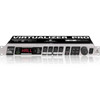
VIRTUALIZER PRO DSP2024P + To assure optimal protection of your DSP2024P during use or transport, we recommend utilizing a carrying case. + Please always use the original packaging to avoid damage due to storage or shipping. + Never let unsupervised children play with the DSP2024P or with its packaging. + Please dispose of all packaging materials in an environmentally-friendly fashion. The BEHRINGER VIRTUALIZER PRO requires one standard 19" rack unit of space (1 3/4"). Please leave an additional 4" installation depth to allow connections at the rear side. Make sure that there is adequate ventilation and do not place the VIRTUALIZER PRO on top of an amplifier, which could cause overheating. + Before connecting the VIRTUALIZER PRO to the mains, carefully check that your equipment is set to the correct voltage: The fuse holder on the female mains connector has 3 triangular markings, with two of these triangles opposing each other. The VIRTUALIZER PRO is set to the operating voltage printed next to these markers and can be set to another voltage by turning the fuse holder by 180°. CAUTION: This instruction does not apply to export models exclusively designed, e.g. for 120-V operation! Connection to the mains is made by a mains cable with an IEC receptacle that complies with the required safety regulations. + Please make sure that the unit is grounded at all times. For your own protection, you should never tamper with the grounding of the cable or the unit itself. The unit shall always be connected to a mains socket outlet with a protective earthing connection. + Installation and operation of this equipment must be carried out by competent staff only. Both before and after installation, the staff using the equipment should make sure that it is properly grounded since otherwise electrostatic discharge etc. can lead to an impairment of its operation. For more information, see chapter 6 “INSTALLATION”. The BEHRINGER VIRTUALIZER PRO is equipped with electronically servo-balanced inputs and outputs. The circuit design features automatic hum suppression for balanced signals and thus ensures trouble-free operation, even at the highest operating levels. Externally induced mains hum, etc. can therefore be effectively suppressed. The automatic servo-function recognizes the presence of unbalanced connectors and adjusts the nominal level internally to avoid level differences between the input and output signals (6-dB correction). The MIDI connectors (IN/OUT/THRU) are standard DIN plug connections. The data communication is isolated from ground by opto-couplers. 1.3 Control elements Fig. 1.1: VIRTUALIZER PRO front panel The BEHRINGER VIRTUALIZER PRO’s front panel includes five edit controls (non-intermittent rotary controls), a jog wheel (big rotary control), six parameter keys, an LED display and a mains switch. Each of the two fully independent channels can be monitored with an 8-digit LED meter. 1. INTRODUCTION 7
-
 1
1 -
 2
2 -
 3
3 -
 4
4 -
 5
5 -
 6
6 -
 7
7 -
 8
8 -
 9
9 -
 10
10 -
 11
11 -
 12
12 -
13
-
14
-
15
-
16
-
17
-
18
-
19
-
20
-
21
-
22
-
23
-
24
-
25
-
26
-
27
-
28
-
29
-
30
-
31
-
32
-
33
-
34
-
35
-
36
-
37
-
38
-
39
-
40
-
41
 |
 |
