Behringer XENYX 1832FX Manual - Page 3
CONTROL ELEMENTS AND CONNECTORS, The user's manual, Before you get started, Mono channels
 |
View all Behringer XENYX 1832FX manuals
Add to My Manuals
Save this manual to your list of manuals |
Page 3 highlights
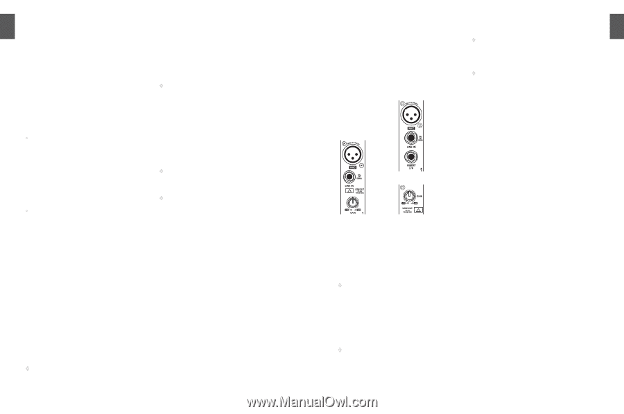
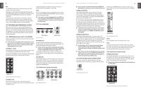
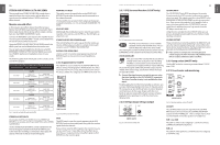
ENGLISH 4 XENYX 1622FX/1832FX/2222FX/2442FX User Manual Level-setting Signals fed into the mixer using a DI-box (Direct Injection) or the output of a sound card or a keyboard, often have to be adjusted to the operating level of your mixing console. Frequency response correction Using the equalizers found in each channel strip, you can simply, quickly and effectively adjust the way a signal sounds. Effects mixing In addition to the effects processor contained in your mixer, using the insert connectors on the mono channels and both aux busses lets you insert additional signal processors into your signal path. • Signal distribution: Individual signals adjusted at each channel strip are laid out at the aux sends and returns, and are either fed into external effects processors or fed back to the internal effects processor. Then, the signals are brought back into the main mix either via the aux return connectors or via direct internal wiring. The mix for the on-stage musicians is also created using the aux sends (monitor mix). Similarly, for example, signals for recording equipment, power amplifiers, headphones and 2-track outputs can also be taken. • Mix: All other mixing console functions fall under this vital category. Creating a mix means primarily adjusting the volume levels of individual instruments and voices to one another as well as giving them the appropriate weight within the overall frequency spectrum. Likewise, you'll have to sensibly spread individual voices across the stereo image of a signal. At the end of this process, adjusting the level of the entire mix to other equipment in the signal path is required (e. g. recorder/crossover/amplifier). The control surface of BEHRINGER mixing consoles is opti-mized in such a way that these functions become easy to fulfil while the signal path remains simple to follow. 1.2 The user's manual The user's manual is designed to give you both an overview of the controls, as well as detailed information on how to use them. In order to help you understand the links between the controls, we have arranged them in groups according to their function. If you need to know more about specific issues, please visit our website at http://www.behringer.com. Additional information and explanations about various music industry/audio technology terminology can be found on individual product pages as well as in the glossary. ◊ The block diagram supplied with the mixing console gives you an overview of the connections between the inputs and outputs, as well as the associated switches and controls. 1.3 Before you get started 1.3.1 Shipment Your mixing console was carefully packed in the factory to guarantee safe transport. Nevertheless, we recommend that you carefully examine the packaging and its contents for any signs of physical damage, which may have occurred during transit. ◊ If the unit is damaged, please do NOT return it to us, but notify your dealer and the shipping company immediately, otherwise claims for damage or replacement may not be granted. 1.3.2 Initial operation Be sure that there is enough space around the unit for cooling purposes and to avoid over-heating please do not place your mixing console on high-temperature devices such as radiators or power amps. The console is connected to the mains via the supplied cable. The console meets the required safety standards. Blown fuses must only be replaced by fuses of the same type and rating. ◊ Please note that all units must be properly grounded. For your own safety, you should never remove any ground connectors from electrical devices or power cables, or render them inoperative. ◊ Please ensure that only qualified people install and operate the mixing console. During installation and operation, the user must have sufficient electrical contact to earth, otherwise electrostatic discharges might affect the operation of the unit. 1.3.3 Online registration Please do remember to register your new BEHRINGER equipment right after your purchase by visiting www.behringer.com (alternatively www.behringer.de) and kindly read the terms and conditions of our warranty carefully. Should your BEHRINGER product malfunction, our goal is to have it repaired as quickly as possible. To arrange for warranty service, please contact the retailer from whom the equipment was purchased. Should your BEHRINGER dealer not be located in your vicinity, you may directly contact one of our subsidiaries. Corresponding contact information is included in the original equipment packaging (Global Contact Information/European Contact Information). Should your country not be listed, please contact the distributor nearest you. A list of distributors can be found in the support area of our website (www.behringer.com). Registering your purchase and equipment with us helps us process your repair claims quicker and more efficiently. Thank you for your cooperation! XENYX 1622FX/1832FX/2222FX/2442FX User Manual 5 2. CONTROL ELEMENTS AND CONNECTORS This chapter describes the various control elements of your mixing console. All controls, switches and connectors will be discussed in detail. 2.1 Mono channels 2.1.1 Microphone and line inputs XENYX2222FX XENYX2442FX Fig. 2.1: Connectors and controls of mic/line inputs MIC Each mono input channel offers a balanced microphone input via the XLR connector and also features switchable +48 V phantom power supply for condenser microphones. The XENYX preamps provide undistorted and noise-free gain as is typically known only from costly outboard preamps. ◊ Please mute your monitor system before you switch on phantom power. Otherwise potentially damaging thumps will be sent to your speakers. Please also note the instructions in chapter 5.5 "Voltage supply, phantom power and fuse". LINE IN Each mono input also has a balanced line input on a ¼" jack. You can also connect unbalanced devices using mono jacks to these inputs. ◊ Please remember that you can use either the microphone input or the line input of a channel, but not both at the same time! INSERT ◊ Insert points enable the processing of a signal with dynamic processors or equalizers. They are sourced pre-fader, pre-EQ and pre-aux send. Detailed information on using insert points can be found in chapter 5.3. ◊ Unlike the 2442FX, the 1622FX, 1832FX and 2222FX have their insert points located on the rear of the console. GAIN Use the GAIN control to adjust the input gain. This control should always be turned fully counter-clockwise whenever you connect or disconnect a signal source to one of the inputs. The scale has 2 different value ranges: the first value range (+10 to +60 dB) refers to the MIC input and shows the amplification for the signals fed in there. The second value range (+10 to -40 dB) refers to the line input and shows its sensitivity. The settings for equipment with st andard line-level signals (-10 dBV or +4 dBu) look like this: While the GAIN control is turned all the way down, connect your equipment. Set the GAIN control to the external devices' standard output level. If that unit has an output signal level display, it should show 0 dB during signal peaks. For +4 dBu, turn up GAIN slightly, for -10 dBV a bit more. Fine-tuning of a signal being fed in is done using the level meter. To route the channel signal to the level meter, you have to press the SOLO switch and set the MODE switch in the main section to PFL (LEVEL SET). Using the GAIN control, drive the signal to the 0-dB mark. This way you have a vast amount of drive headroom for use with very dynamic signals. The CLIP display should light up only rarely, preferably never. While fine-tuning, the equalizer should be set to neutral. LOW CUT Additionally, the mono channels of the mixing consoles have a high-slope LOW CUT filter for eliminating unwanted, lowfrequency signal components (75 Hz, 18 dB/octave). 2.1.2 Equalizer All mono input channels have a 3-band equalizer with semiparametric mid bands. All bands provide boost or cut of up to15 dB. In the central position, the equalizer is off (flat). The circuitry of the British EQs is based on the technology used in the best-known top-of-the-line consoles and providing a warm sound without any unwanted side effects. The result are extremely musical equalizers which, unlike simple equalizers, cause no side effects such as phase shifting or bandwidth limitation, even with extreme gain settings of ±15 dB. ENGLISH
-
 1
1 -
 2
2 -
 3
3 -
 4
4 -
 5
5 -
 6
6 -
 7
7 -
 8
8 -
 9
9 -
10
-
11
-
12
 |
 |