Behringer XENYX 802 User Manual - Page 8
Installation - power adapter
 |
View all Behringer XENYX 802 manuals
Add to My Manuals
Save this manual to your list of manuals |
Page 8 highlights
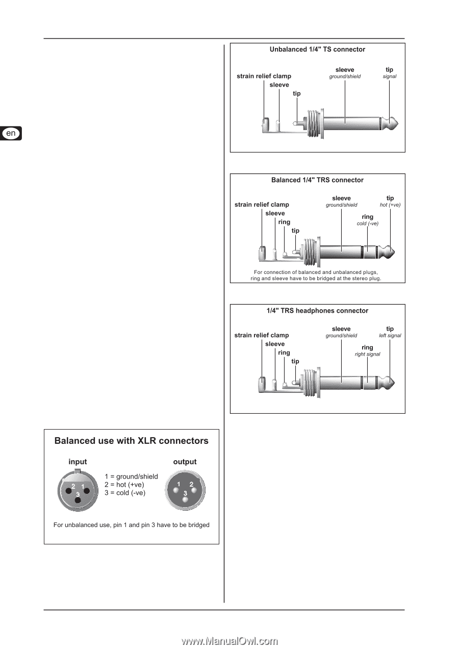
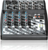
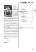
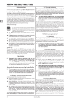
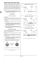
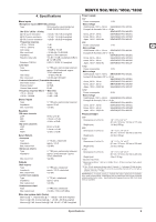
XENYX 502/802/1002/1202 tions (0 dB). Then use the TRIM controls to increase the input amplification until signal peaks show 0 dB on the level meter. When recording to digital recorders, the recorder's peak meter should not go into overload. While analog recorders can be overloaded to some extent, creating only a certain amount of distortion (which is common and often desirable), digital recorders distort quickly when overloaded. In addition, digital distortion is not only undesirable, but also renders your recording completely useless. ++ The peak meters of your XENYX display the level virtually independent of frequency. A recording level of 0 dB is recommended for all signal types. 3. Installation 3.1 Mains connection AC POWER IN Connect the power supply to the 3-pin mains connector on the rear of the console. Use the AC adapter supplied to connect the console to the mains. The adapter complies with all applicable safety standards. ++ Please use only the power supply unit provided with the console. ++ Never connect the XENYX to the power supply unit while the latter is connected to the mains! First connect the console to the power supply unit, then connect the power supply unit to the mains. ++ Please note that both the power supply unit and the mixing console heat up considerably during operation. This is completely normal. 3.2 Audio connections You will need a large number of cables for different applications. The illustrations below show how the connectors should be wired. Be sure to use only high-grade cables. Please use commercial RCA cables to connect the 2-track inputs and outputs. You can, of course, also connect unbalanced devices to the balanced inputs/outputs. To do this, use either mono plugs or stereo plugs with the ring and sleeve bridged (pins 1 and 3 in the case of XLR connectors). ++ Caution! Never use unbalanced XLR connectors (PIN 1 and 3 connected) on the MIC input connectors when using the phantom power supply. Fig. 3.2: 1/4" mono plug Fig. 3.3: 1/4" stereo plug Fig. 3.4: Stereo plug for headphones connection Fig. 3.1: XLR connections 8 Installation
-
 1
1 -
2
-
 3
3 -
 4
4 -
 5
5 -
 6
6 -
 7
7 -
 8
8 -
 9
9 -
 10
10 -
 11
11
 |
 |